What’s the difference, and why does it matter?
Euler angles are generally what most people consider when they picture 3D space. Each value represents the rotation in degrees (it could technically be in any unit) around one of the three axes in 3D space. Most of the time, you will want to create angles using Euler angles because they are conceptually more straightforward to understand. The flaw is that Euler angles have a problem known as the gimbal lock that prevents specific rotations when two axes align. The solution: quaternions.
How do you convert between Quaternion and Euler angles?

Define the coordinate system ‘xoyozo‘ to be fixed to the carrier object where ‘xo‘ axis is lateral and directed to the right, ‘yo’ axis is longitudinal and directed forward, ‘zo‘ axis is standard and directed vertically. At the usual installation of the unit on a carrier object, the unit’s appropriate axes should be parallel to the axes, as Fig. 1. shows. Also, it is possible to install the unit in any known position relative to the object with known alignment angles (see APPENDIX B of the unit’s Interface Control Document (ICD) for details).
The Inertial LabsTM unit calculates the orientation of the coordinate system ‘xoyozo’ fixed to the carrier object concerning Cartesian geographical reference frame ‘xyz’ where axes ‘x’ and ‘y’ are in the level and directed to the East and North, and ‘z’ axis is directed up. Such reference frame is also known as ENU (East-North-Up) Earth-level frame.
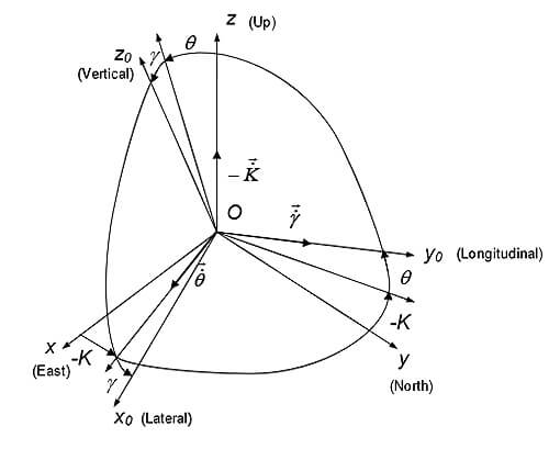
Measured angles are the standard Euler angles of rotation from the Earth-level frame to the object frame: heading K is first, then pitch q, and then roll g — see Fig. 2.
Notes:
- The positive direction of the heading is clockwise. So, heading K is shown with the minus sign in Fig. 2.
- In different applications, “heading” is also known as “azimuth” or “yaw”; “pitch” is also known as “elevation” or “tilt”; and “roll” is also known as “bank.”
Due to the definition of Euler angles, there is a mathematical singularity when the object’s longitudinal y0-axis is pointed up or down (i.e., pitch approaches ±90°). This singularity is absent in the presentation of the quaternion or directional cosine matrix (rotation matrix).
Directional Cosine Matrix (DCM) is the rotation matrix C from the object body reference frame ‘xoyozo‘ to the geographical reference frame ‘xyz’. According to Fig. 1, DCM can be represented through Euler angles as:
\boldsymbol{C}=\left[\begin{array}{ccc} \cos K \cos \gamma+\sin K \sin \gamma \sin \theta & \sin K \cos \theta & \cos K \sin \gamma-\sin K \cos \gamma \sin \theta \\ -\sin K \cos \gamma+\cos K \sin \gamma \sin \theta & \cos K \cos \theta & -\sin K \sin \gamma-\cos K \cos \gamma \sin \theta \\ -\cos \theta \sin \gamma & \sin \theta & \cos \theta \cos \gamma \end{array}\right]</p><p>
Equation 1
Or, Euler angles can be calculated from elements cij of directional cosine matrix C:
K=\arctan \frac{C_{12}}{C_{22}} ; \theta=\arcsin C_{32} ; \gamma=-\arctan \frac{C_{31}}{C_{33}} .
Equation 2
Also the Inertial LabsTM unit provides orientation output in quaternion Q form, which is a hyper-complex number with four components.
\boldsymbol{Q}=\left(q_0, q_1, q_2, q_3\right)
Equation 3
where q0 is real part, q1, q2, q3 are vector part. In other words, q0 represents the magnitude of the rotation, and the other three components represent the axis about which that rotation takes place.
With only four components, the quaternion representation of orientation is computationally efficient. However, manipulation of quaternions is not intuitive, so their use in place of directional cosine matrices may increase the chances of mistakes being made.
Quaternion Q is converted to directional cosine matrix C using the next expressions:
C=\left[\begin{array}{ccc} q_0^2+q_1^2-q_2^2-q_3^2 & 2\left(q_1 q_2-q_0 q_3\right) & 2\left(q_1 q_3+q_0 q_2\right) \\ 2\left(q_1 q_2+q_0 q_3\right) & q_0^2+q_2^2-q_1^2-q_3^2 & 2\left(q_2 q_3-q_0 q_1\right) \\ 2\left(q_1 q_3-q_0 q_2\right) & 2\left(q_2 q_3+q_0 q_1\right) & q_0^2+q_3^2-q_1^2-q_2^2 \end{array}\right]
Equation 4
The reverse conversion from directional cosine matrix C to quaternion Q is following:
\begin{gathered} q_0=\frac{1}{2} \sqrt{1+c_{11}+c_{22}+c_{33}} \\\\ q_1=\frac{c_{32}-c_{23}}{4 q_0}\\\\ q_2=\frac{c_{13}-c_{31}}{4 q_0}\\\\ q_3=\frac{c_{21}-c_{12}}{4 q_0} \end{gathered}
Equation 5
The expressions above in Equation 5 are widely used but have a singularity at q0 = 0. Therefore, the Inertial LabsTM unit uses other expressions that have no singularity:
\begin{gathered} q_0=\frac{1}{2} \sqrt{1+c_{11}+c_{22}+c_{33}} \\\\ q_1=\frac{1}{2} \sqrt{1+c_{11}-c_{22}-c_{33}} \cdot \sin \left(c_{32}-c_{23}\right) \\\\ q_2=\frac{1}{2} \sqrt{1-c_{11}+c_{22}-c_{33}} \cdot \sin \left(c_{13}-c_{31}\right) \\\\ q_3=\frac{1}{2} \sqrt{1-c_{11}-c_{22}+c_{33}} \cdot \sin \left(c_{21}-c_{12}\right) \end{gathered}
Equation 6
At necessity to calculate Euler angles from quaternion, calculate elements c12, c22, c31, c32, c33, according to Equation 6, and then use Equation 2:
\begin{gathered} K=\arctan \frac{2\left(q_1 q_2-q_0 q_3\right)}{q_0^2+q_2^2-q_1^2-q_3^2}\\\\ \theta=\arcsin \left(2 q_2 q_3+2 q_0 q_1\right) \\\\ \gamma=-\arctan \frac{2\left(q_1 q_3-q_0 q_2\right)}{q_0^2+q_3^2-q_1^2-q_2^2} \end{gathered}
Equation 7
Where arctan is a four-quadrant inverse tangent.