Introduction to Remote Sensing and Scanning
Light detection and ranging (LiDAR) sensors are a commonly used source of optical information for remote sensing payloads in scanning and surveying applications. LiDAR payloads use penetrating pulses of laser light that are reflected and used to determine the relative distance to the point that it is reflected from. When these pulses backscatter (reflect at an angle of 180 degrees), many payloads will use inertial navigation systems (INS) to timestamp and georeference data points that are acquired. Compiled together, these individual data points paired with point cloud software streamline the process of analyzing structures and ground planes. Let’s get deeper into the payload solution world.
Industry Analysis Inspections
Power Lines
Regular inspections of power lines are critical for securing uninterrupted power distribution. In the past, ground inspection methods were utilized by a group of surveyors. This method is labor-intensive, time-consuming, and potentially dangerous for teams inspecting lines in hazardous terrain. As of late, energy service providers have begun to turn to automated LiDAR-equipped UAV payload technology. This has proven to be an effective alternative to manual inspection and results in producing highly accurate point cloud data through post-processed kinematic (PPK) and real-time kinematic (RTK) methods. With Inertial Labs’ payload solutions, surveying power lines with an automated payload is a time-efficient and cost-effective alternative to land surveillance.

Construction Site
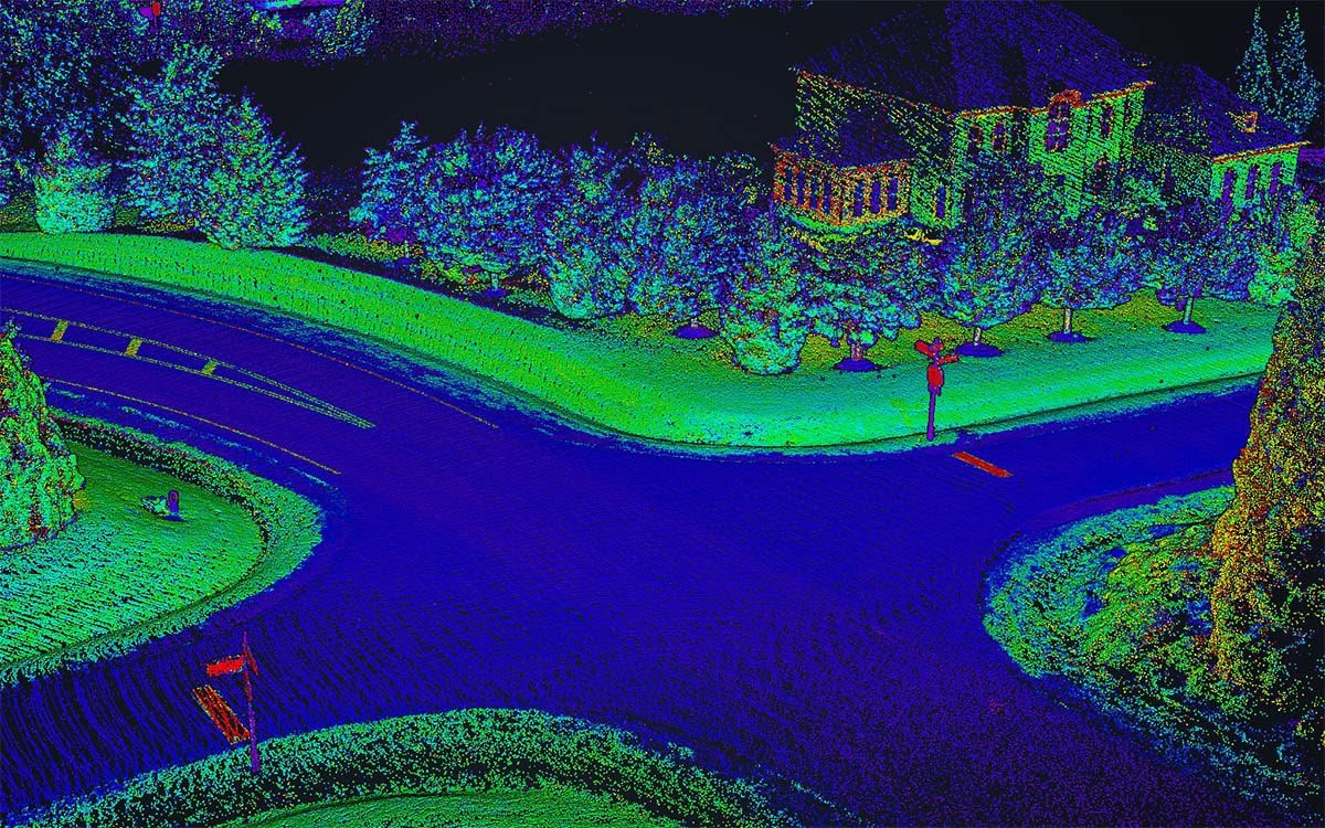
LiDAR systems have a wide range of applications throughout all phases of construction. Even before construction, it is essential to survey the site to confirm that all structures can foundationally exist on the terrain without any structural issues caused by rockslides, uneven terrain, or sinkholes. An efficient way to survey structures and terrain accurately is by using drone aerial surveillance. LiDAR payload solutions can also be a valuable tool in the visualization of elevation, as color schemes can be added to the point clouds, indicating changes in elevation. As a result, the time it takes to create x, y, and z coordinates for structures has been significantly reduced, meaning that 3D analysis of the ground and structures is much easier.
Autonomy and SLAM
The most valuable resource and commodity in this world is time. As our society enters a new age of autonomy, the desire for fully functioning level-5 autonomous vehicles and machinery is beginning to emerge. This comes with a caveat: robots and other autonomous systems cannot always rely on GNSS for navigation, especially indoors, where GNSS signals are unreliable. Whether indoors or outdoors, GNSS-based navigation is not sufficiently accurate for systems that need precision within a few centimeters to operate safely. Systems requiring centimeter-level precision rely on simultaneous localization and mapping (SLAM) to map and discover their surroundings.
Systems utilizing SLAM build their maps in real time. These systems can find their position by aligning sensor data that they collect with previously collected data to build a navigation map. Robots using SLAM continuously gather data at a rapid rate. While camera files are processed at a considerably faster rate when compared to LiDAR files, they lack native information regarding depth and reference frames.
Raw sensor data undergoes a process called sensor fusion employed by a Kalman filter (for more info on sensor fusion, see our white paper), which better estimates how the autonomous platform moves. Inertial Labs considers NVIDIA’s graphics cards the natural next-step integration for future navigation solutions. With an embedded sensor-fused navigation solution and a complementary computer vision algorithm for task recognition and execution, Inertial Labs expects to partner with many developing companies, pushing the ball forward in autonomy.
Cloud Modeling: Acquiring Data
RTK Solutions without Corrections
Many topographic surveying industries or SLAM solutions do not require centimeter-level accuracies in their point cloud solutions. As a result, a Real-Time Kinematic solution is accurate enough without any correctional services being used. RTK data is produced immediately, without time-consuming and complicated post-processing.
As a result, the user can generate models in real-time if they have hardware with a GPU capable of doing so.
At Inertial Labs, our payload solution has been proven to generate repeated RTK point cloud models with 5 centimeters of accuracy (cloud thickness). As a result, our team can confidently market a robust and reliable solution and a system that will produce accurate data in real time, eliminating the need for post-processing.
RTK Solutions with Corrections
Correctional services can considerably increase position and heading accuracies of navigation systems. Presently, there are many services available including NovAtel’s TerraStar, OmniStar, Oceanix, SmartNet, and Sapcorda. All of which are supported by Inertial Labs’ differing product families. Although not all support centimeter-level RTK corrections, all result in removing heading and positional errors between a base station (or network) and a rover.

Heading and position accuracy are the most critical aspects when performing any remote sensing task, as these play vital roles in point cloud precision and accuracy. Typically, correctional information is sent as an RTCM protocol, valid up to approximately 35 kilometers from the base station.
Correction data can be received from either a network of base stations or from the user’s own dedicated local base station. The advent of RTK receivers has made it increasingly easy for users to achieve centimeter-level location data. This is very important for applications requiring precise and accurate data and cannot post-process data – like power line inspections or roadway analysis for sinkholes and asphalt cracking.

Post-Processed Solutions
Post-Processed Kinematic (PPK) is the alternative to RTK in which sub-centimeter position accuracy does not happen in real-time but is achieved through correctional services applied after the data is captured.

Besides enhancing position accuracy, post-processing inertial data also significantly increases a data set’s heading accuracy, arguably the most critical component when generating a final solution. The advantage of PPK is that the rover does not require additional hardware on board to get sub-centimeter position accuracy or a heading accuracy of 0.03 degrees. Standard PPK software can be used to view and analyze data with respect to time in the forward and backward directions.
This means that dual antenna systems are unnecessary, and a surveyor can rely on a single antenna system without worrying about setting up a proper dual antenna baseline for increased heading accuracy. Many PPK software programs require base station data (virtual or physical), inertial data from the rover, and GNSS data (with optional RTCM corrections) to compute the most accurate PPK inertial solution.

When post-processing, both the base station (or ground station) and the UAV record GNSS data, which is combined with inertial data and processed to create accurate positioning and orientation data. Like RTK corrections (as RTCM messages), PPK corrections work best when the rover is closest to the base station. However, atmospheric errors can occur when operating long distances from the base station. Fortunately, many PPK software programs today have built-in functions to help mitigate this error build-up.
Laser File Generation
Additional software is then needed for taking computed trajectory files (computed in real-time from Inertial Labs devices or generated in PPK software) and combining them with the acquired laser data. Inertial Labs supports laser data from many scanners, including Velodyne, Quanergy, Ouster, and Livox. An example of a flight’s trajectory in post-processing software is shown below.

Beginning with the blue part of this trajectory, the rover begins with a straight flight, reaching a set velocity, allowing GNSS heading corrections to begin being filtered into the INS solution. After this straight flight, convergence maneuvers (Figure eight) allow the GNSS heading to be fused properly with inertial data from the IMU used in PPK software. Latter parts of the blue and green portions of the trajectory file are where scanning data is logged and used for cloud generation.
Once the trajectory and scan files have been loaded onto the cloud generation software, the user can configure parameters generating point cloud files. They can select additional portions of the trajectory that they would like to associate with the generated cloud. With this possibility in mind, the user can ensure that the clouds they produce contain reliable data.

Analysis
Once a .las point cloud has been generated, various cloud-viewing software programs are available to analyze the point cloud further and generate conclusive results. For those who want to analyze differences and similarities between multiple acquired clouds, freeware such as CloudCompare offers tools for users to customize profiles and analyze datasets. This will allow users to analyze the thickness of the cloud at both a general level through inspection and at a detailed level. Users can take a cut out of a specific section of a point cloud and rotate the point of view to analyze its thickness. The thickness of a cloud is essential, as it reflects the point cloud’s accuracy. Alternatively, if the user simply wants to view data with minimal manipulation and analysis, freeware like Displaz has proven to be a very effective tool.

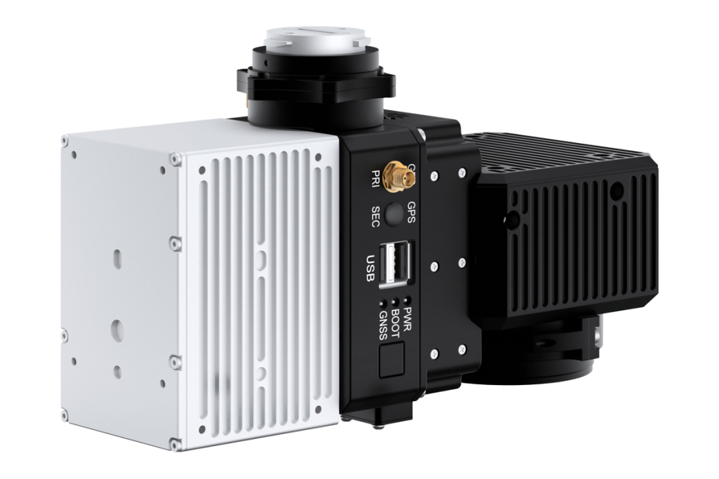
The Remote Sensing Payload Instrument (RESEPI)
Features
Diverse Scanner and Camera Integrations
What sets RESEPI apart from other remote sensing payloads is its customization ability. Each LiDAR scanner may vary in a variety of key specifications, such as maximum AGL, range accuracy, scan rate, and field of view.
Different scanning projects will have different requirements, and many LiDAR scanners will not be able to meet the requirements of all applications. The INS-D-OEM is easily integrated with various of the top LiDAR scanners in the industry, including the Livox Mid-40, Livox Horizon, Velodyne VLP-16, Quanergy M8, and OUSTER OS1.

With the ability to be easily integrated with all these LiDAR scanners, RESEPI can be used in various applications with varying requirements. In addition to the many LiDAR integrations, the RESEPI has also been designed to work with stereo cameras like the Sony A6000 for photogrammetry, and the Blackfly FLIR.
Real-Time Logging
The Inertial Labs RESEPI features a comprehensive interface both in and out of flight. One of the many features of the interface is that it displays what devices are connected, as well as information from the data logger. The data logger will log inertial data, LiDAR data points, base station data, and raw GNSS data. Also, if the RESEPI is integrated with a camera in addition to LiDAR, the interface will show the number of images captured from the camera device. Each data category from the data logger comprises the components necessary for generating a point cloud. If using a real-time solution, data logging features the ability to generate a scan file at the time of scan completion.
Future Development
Current partnerships are directing the RESEPI solution into the world of autonomy. In future releases, the RESEPI could be paired with NVIDIA graphics cards to allow real-time data processing, object recognition, avoidance, and even SLAM-based navigation for the autonomous world. Additionally, RESEPI can be sensor fused with many types of optical data currently limited to stereo cameras. However, with the right partners, RESEPI can be further developed to work with multiple LiDAR scanners, thermal cameras, stereo cameras, infrared cameras, and other sources of optical data.

Why Pay More?
Here is a cost and functional comparison of the RESEPI and similar products from competitors. We understand that every application has a particular set of requirements. Inertial Labs works hard to build a perfect solution for every application while ensuring the customer does not overpay. As you may see from the table, while maintaining similar or better point cloud accuracy, RESEPI is a solution that is much less costly when compared to the competition.

Benefits for Inertial Labs Partners Features
Inertial Labs RESEPI is the perfect solution for new companies looking to get into the remote scanning industry or for existing companies looking to expand their business. Inertial Labs provides custom solutions for entities looking to enter any UAV LiDAR industry subcategory. From power line inspection to construction site monitoring to precision agriculture, Inertial Labs is confident that this platform can be integrated to meet each industry sect.

Value Added Resellers can focus on growing their business rather than developing the payload product. We will support and grow the product together to meet the market requirements with a commitment to supplying the best price/ performance solution to our business partners.
Supply Chain Management
Inertial Labs has 20 years of experience in the positioning and orientation industry, as a result, Inertial Labs has had years to fine-tune and optimize supply chain management. With well-defined roles and an open and collaborative atmosphere, Inertial Labs has fostered a working environment centered upon an efficient flow of information and products. Inertial Labs partners do not need to worry about order fulfillment and supply chain logistics and can focus on business development.
Competitive Pricing
As a current supplier of inertial navigation technology, Inertial Labs can provide the most cost-efficient pricing for partners.
With price discounts for partners and an uncompromising focus on value and quality, we are confident that you will be put in the best position to succeed.
RESEPI in Action
Test Setup
This test was conducted on September 14, 2020, with minimal to no cloud cover, a temperature of 75°F (24°C), and a clear line of sight for satellite visibility. Wind speed varied during the flight from only a few mph up to 5mph.

The RESEPI payload was assembled in-house, calibrated, tested, and verified for performance with the Sony A6000 camera before the flight.
Methods
RTCM corrections were sent to the payload throughout the test to generate point clouds to form RTK and PPK solutions.
After communication over the RESEPI’s onboard WiFi network was established and GNSS connectivity had been verified, the test flight was initialized by sending the command to the onboard flight computer. The scan flight began with a horizontal, straight-line flight reaching a set velocity, allowing GNSS heading corrections to be filtered into the INS solution. After this straight flight, convergence maneuvers (as shown in Figure eight) were done to allow the GNSS heading to be fused properly with inertial data from the IMU and used in PPK software.

The flight path followed a multipath scan pattern, and after the scan was complete, the USB drive that contained all data files needed for processing the clouds was removed from the RESEPI.
Inertial Explorer was used for post-processing inertial data and generating a post-processed trajectory. The in-flight RTK trajectory and the PPK trajectory from Inertial Explorer were imported to software created by Inertial Labs for cloud generation. Then, the point cloud was colorized using the time-stamped photographs taken from the Sony A6000.
Results
The test ultimately concluded with the generation of a colorized point cloud that accurately captured the entirety of the premises. After analyzing the cloud in Displaz, its thickness was within 3-5 centimeters. In addition, the viewer could see thin objects such as power lines.

The Big Picture
Inertial Labs’ newest platform, RESEPI, is a revolutionary one-stop turnkey solution for start- ups in the industry or businesses looking to expand into the rapidly growing LiDAR scanning payload market.
Inertial Labs’ optimized supply chain management and the ability to provide custom integrated solutions gives any partner all the tools they need to grow their business. With a one-click command line interface and the ability to have fully automated RTK LAS file generation, RESEPI continues to push the industry boundaries of what is possible.
RESEPI-LIVOX Avia
The Inertial Labs RESEPI is an ultra-affordable solution for highly accurate Remote Sensing applications. As a small, low-power, and incredibly lightweight system, RESEPI is designed to fit any project’s size and power requirements and allows the user to fly longer and collect more data. In addition, RESEPI’s highly automated software suite with automatic RTK LAS file generation and a 1-click command line interface makes point-cloud generation fast and easy. The RESEPI features multiple integrations and can be used for various industry applications. The RESEPI can accurately inspect power lines and construction sites, perform land and topographic inspections, and survey land for precision agriculture.
Contact Information
Address: 39959 Catoctin Ridge Street, Paeonian Springs, VA 20129 U.S.A.
Website: www.inertiallabs.com