Harnessing the Gyroscope with a Gimbal
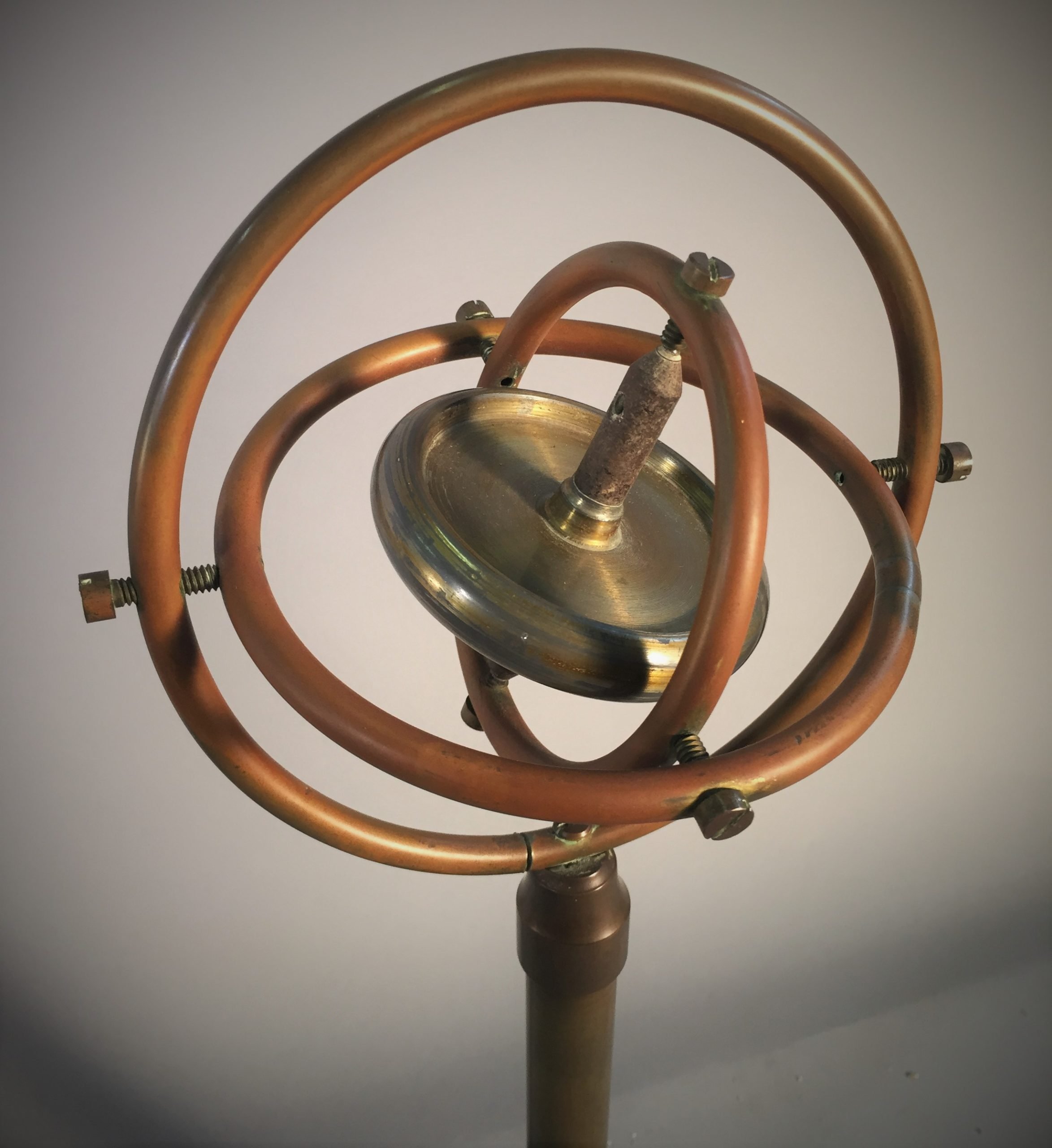
Curious minds sought to delve deeper into this sensation by mounting the spinning disc within a gimbal. A gimbal, an invention dating back several centuries BC, is a frame assembly that allows independent movement between the gimbal frames and the attached object. In this case, the inner gimbal frame, which holds the spinning disc’s axle, is connected orthogonally (at a 90-degree angle) to the outer gimbal frame. Each attachment point between these components uses pivots to minimize friction and preserve gyroscopic effects. The outer gimbal is mounted at the top and bottom using pivots to a frame that can be secured. This results in a configuration we now recognize as the classical mechanical gyroscope, with the gimbals capable of rotation around the X, Y, and Z-axes.
Gyroscopic Motion and Conservation of Angular Momentum
Gyroscopic motion refers to a spinning object’s inherent tendency to preserve its rotational alignment. As an object rotates, it accumulates angular momentum, which must be conserved. Therefore, the object resists any alteration to its axis of rotation, as such changes would necessitate a modification in its angular momentum. With the gimbal arrangement, it becomes evident that the spinning disc’s axis of rotation remains consistent even when the gyroscope itself is rotated or tilted in three-dimensional space. This phenomenon illustrates the conservation of angular momentum of the spinning disc and the resulting forces generated when the gyroscope’s orientation changes. Alterations in the gyroscope’s orientation cause shifts in the positions of the gimbals, allowing the spinning disc to maintain its original axis of rotation. It’s important to note that the faster the disc spins, the greater its angular momentum, making it more resistant to changes in orientation. This reaction to altered orientation likely inspired the concept of using the spinning disc to determine orientation.
The First Practical Use of Gyroscopes in Navigation: The Gyrocompass
The advent of electric motors made it feasible to keep the gyroscope spinning at a consistently high speed, paving the way for its practical use in navigation. In navigation, the idea was to harness and control gyroscopic effects relative to the North, based on the Earth’s axis of rotation. This innovation led to the development of a non-magnetic navigation system. For mariners aboard steel-hulled vessels, a non-magnetic heading source that aligns with true geographical North promised enhanced navigational accuracy and relief from the complexities of traditional celestial navigation or errors associated with magnetic compasses in the presence of ferrous metals. Magnetic North also consistently differs from true North. In pursuit of this goal, Hermann Anschütz-Kaempfe pioneered the “gyrocompass” in the early 20th century. The Anschütz gyrocompass allowed changes in a vessel’s direction (heading) to be determined without relying on a magnetic compass. Gyrocompassing, as it came to be known, could be achieved in various ways, such as encircling the gimbal with a graduated ring to enable gimbal rotation that points to the new direction, much like a magnetic compass needle. Another method involved trapping the gimbal and measuring the torque generated by the gyroscope when its direction changed, allowing for the calculation of rotational movement.
A Glimpse into Inertial Navigation Systems (INS)
The era of the autonomy revolution and the development of vehicles, machines, and systems capable of operating without human intervention necessitates highly reliable navigation, control, and safety systems. At the core of such systems lies the navigation system, often an inertial navigation system (INS). A typical INS provides various navigational and orientation data for a vehicle, including roll, pitch, and heading. This data is obtained through sensors that detect changes in linear acceleration along each axis and gyroscopes for detecting rotation around each axis. Heading information may come from magnetometer-type sensors or a fiber-optic gyroscope. When GNSS (Global Navigation Satellite System) is unavailable as a reference for location, absolute position or location data can be estimated using dead-reckoning, which relies on changes in motion.
Current Gyroscope Sensor Technology
The modern era, marked by advancements in electronics, computing, photonics, and enhanced manufacturing techniques, has significantly transformed gyroscope technology. While the core principles of the gyroscope remain unchanged, the way we design and utilize gyroscopes has evolved over the past century. Our relentless quest for technologies offering superior accuracy, reduced size and weight, and lower costs has driven innovation across a wide range of commercial, industrial, and defense applications. This drive for innovation is further fueled by the growing demand for data gathering and analysis capabilities that enable high-resolution data capture at unprecedented levels.
Inertial Labs TAG-200 and TAG-300


When choosing gyroscopes for your specific application, you should take the following factors into account:
- Accuracy and Precision: Determine the accuracy and precision required for your application. Different gyroscopes may offer varying degrees of accuracy, so match the specifications to your needs.
- Output Format: Consider the output format of the gyroscope data. Some gyroscopes provide analog outputs, while others offer digital outputs like RS-232, RS-485, or USB. Ensure compatibility with your data acquisition system.
- Angular Rate Range: Evaluate the gyroscopes’ angular rate range to ensure it covers the full range of motion or rotation your application requires. It’s essential that the gyroscope accurately measure the rates of interest.
- Size and Form Factor: Consider the gyroscopes’ physical size and form factor. Ensure they can be integrated into your system without causing size or weight constraints.
- Environmental Conditions: Assess the environmental conditions where the gyroscopes will be used. Gyroscopes designed for harsh environments should be chosen if your application requires them, such as those with extended temperature ranges or resistance to shock and vibration.
- Power Consumption: Consider the power requirements of the gyroscopes. Lower power consumption may be crucial for battery-powered applications or when minimizing power usage is essential.
- Calibration and Stability: Determine whether the gyroscopes require frequent calibration and assess their long-term stability. Gyroscopes that maintain accuracy over time can reduce maintenance efforts.
- Integration Capabilities: Check whether the gyroscopes offer compatibility with standard communication protocols and data interfaces used in your industry. Compatibility with software tools for data analysis can also be valuable.
- Cost and Budget: Consider your budget constraints. While meeting your performance requirements is essential, staying within budget is equally important.
- Manufacturer Reputation: Research the reputation of Inertial Labs or any other manufacturer you are considering. Look for customer reviews, case studies, or references to gauge their track record.
- Support and Documentation: Ensure the manufacturer provides adequate technical support and documentation. Good help can be crucial if you encounter issues during integration or operation.
- Customization Options: Inquire about customization options depending on your needs. Some manufacturers offer tailored solutions to meet unique requirements.
- Certifications and Compliance: Verify that the gyroscopes meet any necessary industry certifications and standards, especially if your application has regulatory requirements.
- Warranty: Understand the warranty terms and conditions. A more extended warranty period can provide peace of mind.
- Compatibility with Other Sensors: If your application involves multiple sensors (e.g., accelerometers, magnetometers), consider how well the gyroscopes integrate with these other components.
Here are some specific recommendations for Inertial Labs gyroscopes:
- TAG-200: The TAG-200 is a two-axis gyroscope ideal for stabilization and pointing applications in land vehicles and robotics. It is small, lightweight, and has low power consumption.
- TAG-300: The TAG-300 is a three-axis gyroscope ideal for aerospace and defense stabilization and pointing applications. It is also well-suited for robotic applications that require high performance and reliability.
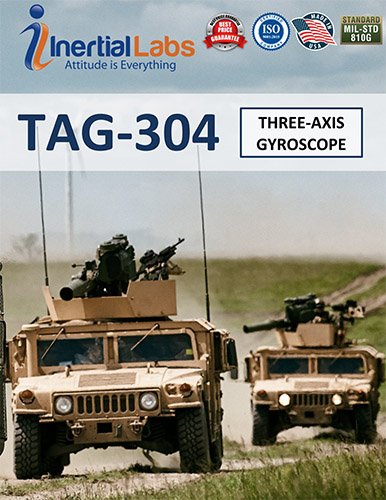
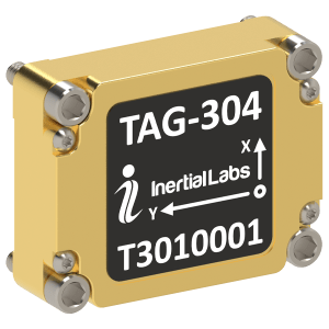
- TAG-304: The TAG-304 4 is a Three-axis Gyroscope developed for different platforms: Guidance and navigation and Electro-Optical Systems, Gimbals, Line-Of-Site, and Pan and tilt platform stabilization and pointing applications.
- IMU-P: The IMU-P is an inertial measurement unit (IMU) that contains three gyroscopes and three accelerometers. IMUs measure an object’s orientation, velocity, and acceleration. The IMU-P is a good choice for applications that require all six degrees of freedom (DOF) of motion data.
- Kernel-100: The Kernel-100 is a small, lightweight, and low-cost IMU that is ideal for a variety of applications, including drones, robotics, and industrial automation.