Abstract
Accurate measurement of roll and pitch is essential in various systems and applications since these angles describe the spatial orientation of an object relative to the horizon and directly affect its stability, control, and safety. Errors in their measurement can lead to incorrect decisions and even emergencies in a variety of critical systems. This paper examines the basic principles of roll and pitch measurement and emphasizes the importance of their accurate measurement.
The sections will cover Introduction to Pitch and Roll Measurement and The Inertial Labs Single and Dual Antenna GPS-Aided Inertial Navigation System – INS. The conclusion will summarize the benefits of using INS for navigation.
Section 1. Introduction to Pitch and Roll Measurement
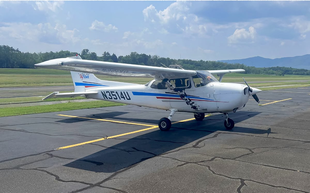
In aviation, roll, and pitch determine the orientation of an aircraft in the air. Measurement errors can lead to incorrect position estimates, which are critical for autopilots and maneuvers. Precise control of roll and pitch is also essential to prevent dangerous situations such as stalls or loss of lift. Drones use roll and pitch data to stabilize and adjust their trajectory.
For motorcycle electronic stability systems (such as ABS or traction control), it is vital to consider roll angles to correctly distribute braking forces and control acceleration. In robotics, especially for robots moving on complex surfaces (such as drones or walking robots), it is crucial to know the roll and pitch angles to maintain balance and avoid falling. Errors in these measurements can lead to incorrect movement or loss of orientation of the robot. Roll and pitch are essential for ships and boats, especially in difficult weather conditions. Ship stabilization systems must accurately measure these angles to maintain wave stability and prevent capsizing or loss of control.
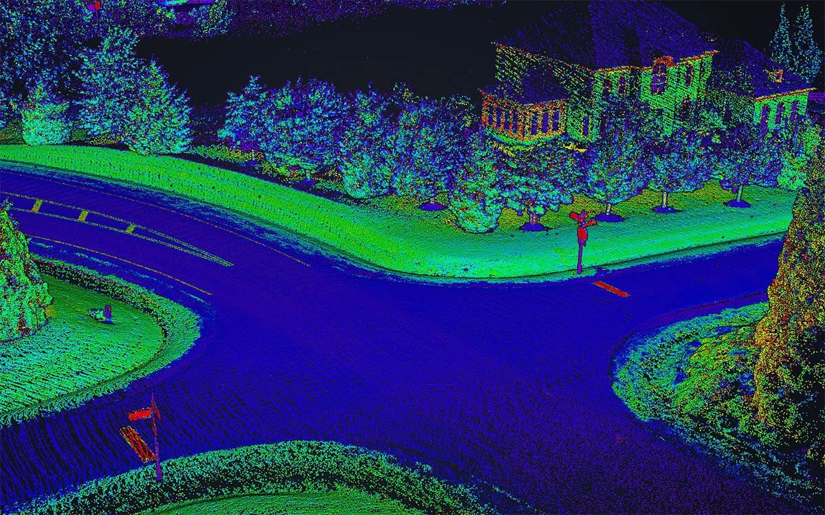
In laser scanning or photogrammetry systems, the roll and pitch of devices mounted on aircraft or vehicles must be accurately measured to ensure accurate terrain or object data. Measurement errors can distort point clouds or maps.
Thus, accurate pitch and roll measurement is vital to safety, control, and navigation in various inertial navigation system applications.
Let’s consider how roll and pitch angles are measured in inertial navigation systems. Accelerometer signals are used to determine roll and pitch. Since the accelerometer measures acceleration, including gravity, its signals can estimate tilt angles relative to the horizontal plane. Figure 1 shows an accelerometer as a parallelepiped, the Z axis of which coincides with the direction of gravitational acceleration.

Figure 1. Conventional designation of the accelerometer.
Assuming the device is stationary and measures only gravity, the accelerometer values can determine the tilt angles. A portion of the gravitational acceleration will be projected onto the X and Y axes when the accelerometer is tilted. In this way, the Pitch and Roll tilt angles can be determined using simple formulas (1).
 (1)
(1)
Without tilt (accelerometer in horizontal position), the force of gravity will be projected mainly on the Z axis. If the device tilts around the Y axis (Pitch), part of the gravitational acceleration will be projected on the X axis. If the device tilts around the X axis (Roll), part of the acceleration will be projected on the Y axis. Thus, the projections of gravitational acceleration on the Y and X axes of the accelerometer allow us to determine the roll and pitch angles. These formulas describe the simplest way to assess Pitch and Roll when tilting about one axis at a time. In the case when the accelerometer is tilted in several axes at the same time, the calculation is more complicated. In this case, the angles can be found using rotation matrices, Figure 2. Matrices of elementary rotations describe the rotation of an object around the X, Y, and Z axes, in our case, the accelerometer axes [1].

Figure 2. Rotation matrices.
The resulting matrix R is the product of the elementary rotation matrices. Using this matrix, the Pitch and Roll angles are found using formula (2).
 (2)
(2)
Formulas (1) and (2) work correctly if the device is stationary or moving at a constant speed (no acceleration). In the case of dynamic motion, when additional accelerations act on the device (for example, when accelerating, braking, or driving around a curve), the accelerometer data will include both a motion acceleration component and a gravity component. This will create false signals that can distort the roll and pitch angle calculations.
To eliminate these problems during dynamic movement, combined methods are used, using data from both the accelerometer and other sensors:
1) Using a gyroscope. A gyroscope measures the angular velocity of a device, allowing it to track orientation changes directly without taking linear accelerations into account. Gyroscope data is more reliable for monitoring roll and pitch angles in dynamic motion.
2) Complementary filter. It combines data from the accelerometer (for slow orientation changes) and the gyroscope (for fast orientation changes), which allows for compensation of errors from each sensor, Figure 3. The accelerometer provides long-term stability, and the gyroscope provides short-term accuracy [2].
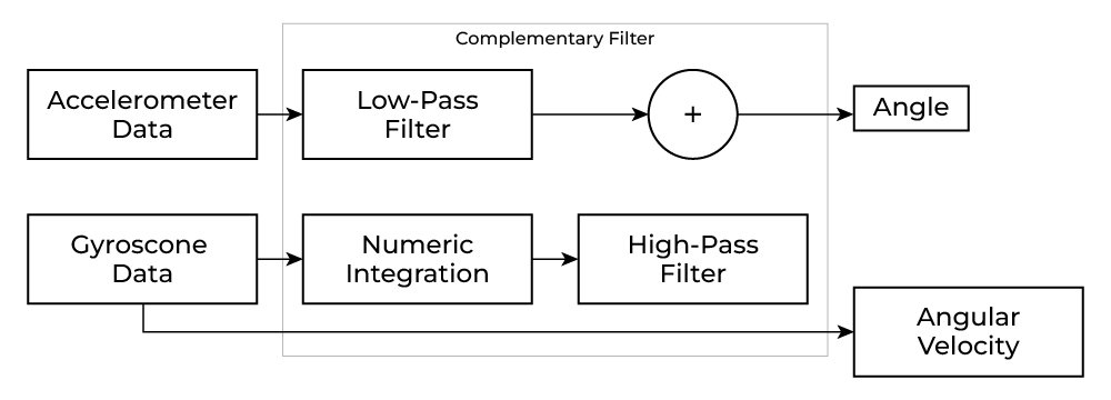 Figure 3. Complementary filter.
3) Kalman filter. This is one of the most common sensor fusion methods [3]. It combines data from the accelerometer and gyroscope to separate motion-induced accelerations from the constant gravitational acceleration. The Kalman filter uses a model of the object’s motion and updates estimates based on previous states and current measurements, allowing for more accurate orientation estimation during dynamic movements.
Thus, the accelerometer alone cannot provide accurate roll and pitch data under dynamic conditions because of additional accelerations. To accurately estimate the orientation, it is necessary to use a gyroscope and sensor fusion algorithms such as the Kalman filter or complementary filter. An example of such a system is INS from Inertial Labs, which will be discussed in detail in the next section.
Section 2. The Inertial Labs Single and Dual Antenna GPS-Aided Inertial Navigation System – INS
The Inertial Labs Single and Dual Antenna GPS-Aided Inertial Navigation System – INS is a new generation of fully integrated, combined GPS, GLONASS, GALILEO, QZSS, BEIDOU, and L-Band navigation and high-performance strapdown system that determines position, velocity and absolute orientation (Heading, Pitch, and Roll) for any device on which it is mounted. Horizontal and Vertical Position, Velocity, and Orientation are accurately determined for both motionless and dynamic applications, Figure 4 [4].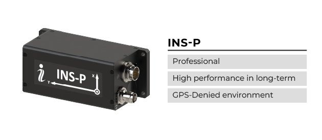
 Figure 4. INS features.
The Inertial Labs INS utilizes advanced single and dual antenna GNSS receiver, barometer, and 3-axes, each calibrated in full operational temperature range precision Fluxgate magnetometers, Accelerometers, and Gyroscopes to provide accurate Position, Velocity, Heading, Pitch, and Roll of the device under measure, Figure 5. INS contains Inertial Labs’ new onboard sensors fusion filter, state-of-the-art navigation and guidance algorithms, and calibration software.
The professional model of INS, the INS-P, utilizes an embedded, high-precision, gyro-compensated magnetic compass, which allows the navigation system to measure and output high-precision Heading without GNSS signal even in extreme environmental conditions (temperature, vibration, interference from external magnetic field).
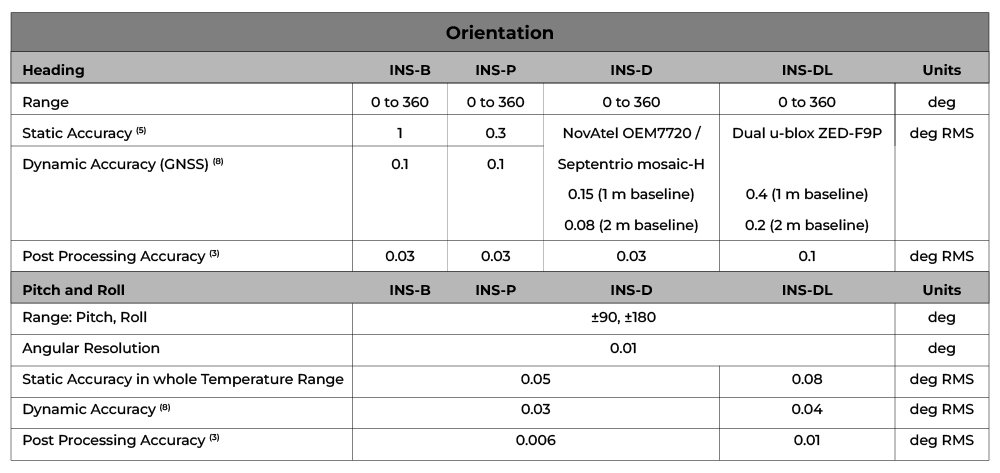 Figure 5. Orientation accuracy.
The newest Inertial Navigation System (INS) from Inertial Labs, the INS-FI, is a GPS-aided system that incorporates several integrated technologies: FOG IMU (Fiber Optic Gyroscope Inertial Measurement Unit), AHRS (Attitude and Heading Reference System), INS (Inertial Navigation System), and an Embedded ADC (Air Data Computer). These technologies provide highly accurate and reliable navigation and orientation data, even in challenging environments, Figure 6.
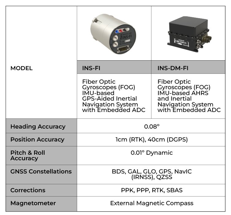 Figure 6. The INS-FI, INS-DM-FI models.
A distinctive feature of Inertial Labs systems is their exceptional accuracy. By integrating advanced algorithms and sensor fusion techniques, their products provide highly accurate location, speed, and orientation data in challenging environments. The ability of the systems to incorporate data from a multi-constellation GNSS receiver offers comprehensive global coverage and immunity to signal failures.
Conclusion
Pitch and Roll measurements are essential in the orientation and navigation of any vehicle, aircraft, or vessel. The accuracy will determine the control quality in autopilot systems or the ability to maintain balance and maneuverability. It is also essential for laser scanning and photogrammetry systems since the accuracy of the orientation will directly affect the accuracy of the point cloud or terrain map.
For a better understanding of the measurement process, the basic principles underlying inertial navigation systems were considered. As was additionally considered, more complex algorithms are used, such as the Kalman filter, which significantly reduces noise and harmful effects.
Inertial navigation systems such as INS from Inertial Labs allow you to get high accuracy of orientation angles at an affordable price. A high-accuracy class of gyroscopes, accelerometers, and productive algorithms will give you a pitch and roll accuracy of 0.01 deg, which is sufficient for various applications.
Inertial Labs is committed to providing high-quality, customizable solutions that are of excellent value for money at an affordable price.
References
[1] Wikipedia Contributors. “Rotation Matrix.” Wikipedia, Wikimedia Foundation, 21 Oct. 2019, en.wikipedia.org/wiki/Rotation_matrix.
[2] Gui, Pengfei, et al. “MEMS Based IMU for Tilting Measurement: Comparison of Complementary and Kalman Filter Based Data Fusion.” 2015 IEEE 10th Conference on Industrial Electronics and Applications (ICIEA), June 2015, https://doi.org/10.1109/iciea.2015.7334442.
[3] Wikipedia Contributors. “Kalman Filter.” Wikipedia, Wikimedia Foundation, 27 Mar. 2019, en.wikipedia.org/wiki/Kalman_filter.
[4] “INS – GPS-Aided Inertial Navigation Systems.” Inertial Labs, 13 Aug. 2024, inertiallabs.com/products/ins-inertial-navigation-systems/.