This manual provides step-by-step instructions to ensure a seamless update process, improving the performance and functionality of your device.
Firmware updates are essential for optimizing the IMU-P firmware capabilities, ensuring compatibility with the latest systems, and addressing potential improvements or fixes. Whether you’re a first-time user or an experienced professional, this guide is designed to support you through the process with clear, concise, and actionable instructions.
By following the steps outlined in this manual, you can enhance the reliability and precision of the IMU-P, ensuring it meets the demands of your specific application. Let’s get started!
Preface.
This manual describes the procedure for updating the firmware of Inertial Labs IMU-P devices. The procedure differs depending on the serial number of IMU-P. For devices with serial numbers I1710011 and lower – please refer to clause #2; for devices with serial numbers I1710012 and higher – please refer to clause #1.
Clause 1. This is for devices with serial numbers I1710012 and higher.
1.1 Required tools:
Flash Loader Demo software (supplied by IL with firmware file);
Flash Loader Demo installation files (provided by IL).
1.2 Required equipment:
IMU-P unit;
IMU-P single port data cable;
RS422 to USB converter;
12V DC power supply;
PC with Windows 7 or higher.
1.3 Procedure
1.3.1 Unzip the file en.flasher-stm32.zip and run the flash_loader_demo_v2.8.0.exe.
1.3.2 Install the software as the wizard guides; do not run it after installation. Reboot the PC.
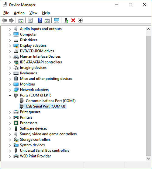
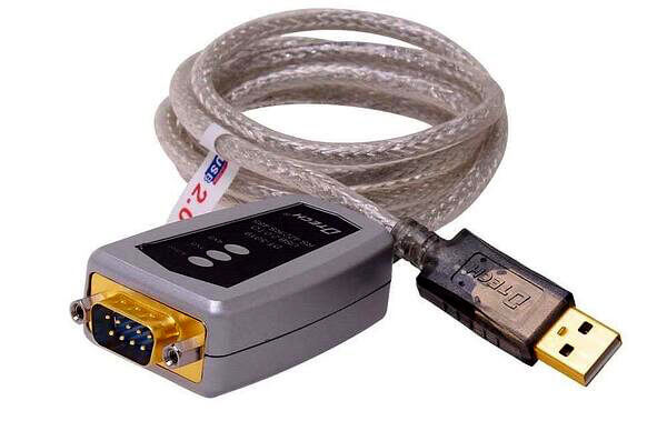
1.3.3 Connect the USB-to-RS422 converter to the PC and install the required drivers. Ensure a new serial port appears in your system by opening “Device Manager.” If connected properly, the converter will show results similar to those in Figure 1.3.3.b.
Figure 1.3.3a. USB to RS422 Converter
Figure 1.3.3b. Device Manager displaying serial port
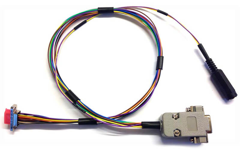
1.3.4 Connect the IMU-P cable to the RS422 adapter and the IMU-P unit. Do not connect the power at this step. See Figure 1.3.4.
Figure 1.3.4. IMU-P single port data cable
1.3.5 Run the file IMUP_1_1_X_X_YYYYMMDD.bat (it is located in the Flash Loader Demo folder). The WIN32 window will appear, asking for the serial port.
Figure 1.3.5. Firmware upload application asks for serial port number.
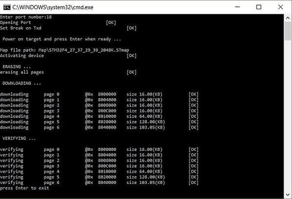
1.3.6 Enter the proper port number as seen in “Device Manager” (reference Figure 1.3.3b). You’ll be asked to power on the device. Do so using a 12V power supply and press Enter. You will see the results in Figure 1.3.6 if everything is set up correctly. Hit Enter to exit the firmware update application.
Note: If the system fails to upload the firmware, try again. Several attempts may be required.
Figure 1.3.6. Successful firmware update
1.3.7 Power cycle (turn off, then on again) the device again, and it is ready to work.
Clause 2. This is for devices with serial numbers I1710011 and lower.
2.1 Required tools:
Flash Loader Demo software (supplied by IL with firmware file);
Flash Loader Demo installation files (provided by IL).
Real Term. 2.0 software (supplied by IL).
2.2 Required equipment:
IMU-P unit;
IMU-P dual port data cable;
RS422 to USB converter;
RS232 to USB converter;
12V DC power supply;
PC with Windows 7 or higher.
2.3 Procedure
2.3.1 Unzip the file en.flasher-stm32.zip and run the flash_loader_demo_v2.8.0.exe.
2.3.2 Install the software as the wizard guides; do not run it after installation. Reboot the PC.
2.3.3 Connect the USB to RS422 converter to the PC and install the drivers if required. Make sure the new serial port appears in your system. Remember the number of this port; let’s assume it is COM1.
Figure 2.3.3. USB to RS422 Converter
2.3.4 Connect the USB to RS232 converter to the PC and install the drivers if required. Make sure the new serial port appears in your system. Remember the number of this port; let’s assume it is COM2.
Figure 2.3.4. USB to RS422 COM2
2.3.5 The data cable you need for the firmware update is shown below. It differs from the cable shown in the first clause because it has 2 DB9 connectors. See picture below.
Figure 2.3.5. IMU-P dual port data cable
2.3.6 Connect the IMU-P cable to RS422 and RS232 adapters and the IMU-P unit. Do not apply the power at this step. See Picture 2.3.6.
Figure 2.3.6. IMU-P data cable and converters
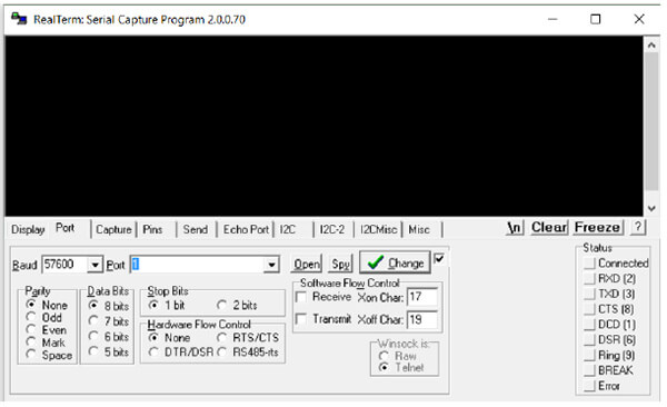
2.3.7 Install and run the Real Term. 2.0. Open the port related to the RS422 adapter (in this example, COM1) at any baud rate. See picture below.
Figure 2.3.7. COM1 opened with 5 Real Term. 2.0
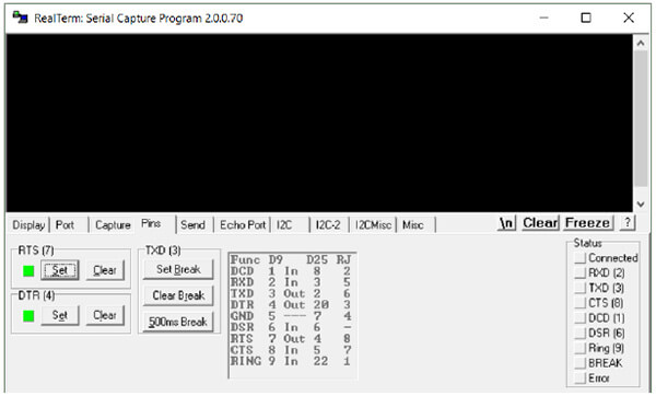
2.3.8 Switch to the Pins tab and press Set Brake.
Picture 2.3.8. Pins tab and Set Break button
2.3.9 Power up the IMU-P, press Clear Brake, and close Real Term. The unit is now in the update mode.
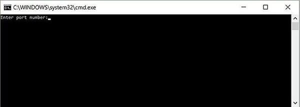
2.3.10 Run the file IMUP_1_1_X_X_YYYYMMDD.bat (it is located in the Flash Loader Demo folder). The WIN32 window will appear, asking for the serial port.
Picture 2.3.10. Firmware upload application asks for serial port number.
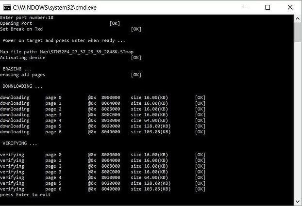
Picture 2.3.11. Successful firmware update
2.3.11 Enter the proper port number related to the RS232 converter. In this example, it is COM2. You’ll be asked to power on the device. It is already powered, so press Enter. You’ll see the result if everything is OK, as shown in picture 2.3.11 above. Hit Enter to exit the firmware update application.
If the system fails to upload the firmware – turn the IMU-P power off and try again starting from section 2.3.7. Several attempts may be required.
2.3.12 After successfully uploading the firmware, power cycle the device again, and it is ready to work.
Website maintenance has been scheduled for Sunday, April 2 from 7 am to 9 pm EDT. The resource may be unavailable at this time. Please accept our apologies for any inconvenience.