INS integration with flight controller based on PX4 firmware
Purpose: Learn how to integrate the INS with the FC based on PX4 firmware Last Updated: August 2025 Author: Oleh Omelianenko
Pixhawk is an independent open-hardware project providing autopilot hardware designs. The Inertial Labs INS can be integrated with a flight controller (FC) based on PX4 firmware. There are two levels of this integration:
Mode 1: Source of raw sensor data
Mode 2: External INS
The installation and connection of the INS and the FC Hardware
It is essential to ensure that the INS and the FC are properly mounted and precisely aligned with the axes of the carrier object. Follow these steps to perform the necessary installation:
Step 1. INS mounting and axis alignment.
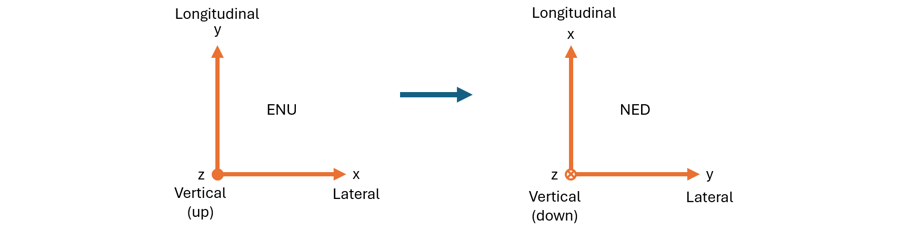
The INS device can be mounted in any orientation. Once mounted, perform the standard alignment procedure to align the INS axes with the carrier object frame. For detailed instructions, refer to Appendix A of the INS ICD. By default, the INS uses an East-North-Up (ENU) body frame, while the FC typically operates with a North-East-Down (NED) coordinate system. Once the INS is aligned with the carrier object frame and connected to the FC, the PX4 algorithm automatically performs an ENU-to-NED transformation to synchronize the two systems. No actions from the end user are needed for this.
Fig.1 ENU-to-NED axes transformation
Step 2. FC mounting and axis alignment.
Mount the FC and, if necessary, perform the alignment procedure to align the FC axes with the carrier object frame. For detailed instructions, refer to the official PX4 firmware developer website.
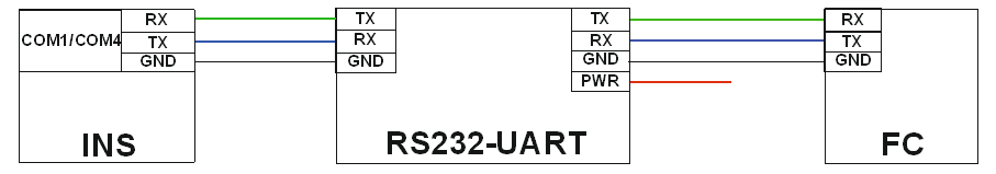
The COM port of the INS must be connected to any unused flight controller serial interface, such as a spare GPS or TELEM slot of the PX4-based FC. The general connection scheme between INS and FC can be seen in Fig.2.
Fig.2 INS to FC connection scheme
The INS configuration
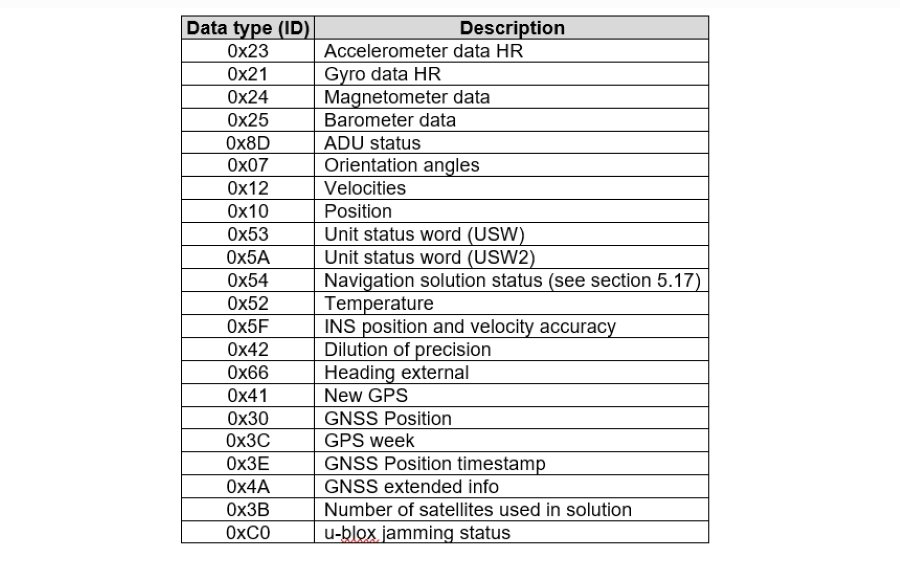
Regardless of which integration level is used, the INS must be configured to output a specific set of binary data via the UDD. The required UDD data set is detailed in Fig.3 . The order of individual data types does not matter. The total message length is 169 bytes.
Fig.3 The required UDD data set
The INS can transmit UDD packets through either its COM1 or COM4 ports. For the COM4 configuration, the ‘INS Data Format’ option needs to be used and adjusted accordingly. The recommended parameters for the chosen COM port are 200 Hz (maximum possible) at 921600 bps. The altitude reference used by the INS and PX4 should be consistent. By default, the INS calculates and outputs altitude relative to the WGS84 ellipsoid, but it is strongly recommended to provide altitude to the FC relative to MSL. This can be configured using the Altitude_var parameter (code 0x13).
The FC configuration
To communicate correctly with the INS, regardless of the integration level, the PX4 firmware must be built with the dedicated Inertial Labs module. Detailed build instructions and further configuration settings are available on the official PX4 firmware developer website.
An examples of the flights with the INS itegrated with the flight controller based on the PX-4 firmware can be seen below:
If you have any questions or inquiries or require further information about Inertial Labs’ cutting-edge technologies, navigation solutions, or our extensive range of products and services, please don’t hesitate to reach out. Our dedicated team of experts is here to assist you. We value your curiosity and are committed to providing comprehensive answers and guidance to address your needs. Contact us today, and let’s embark on a journey of innovation and precision together. Your success is our priority, and we look forward to hearing from you.
Website maintenance has been scheduled for Sunday, April 2 from 7 am to 9 pm EDT. The resource may be unavailable at this time. Please accept our apologies for any inconvenience.