Disclaimer
Information in this document is provided solely in connection with Inertial Labs products. Inertial Labs reserves the right to make changes, corrections, modifications, or improvements to this document and the products and services described herein at any time, without notice.
Trademark legal notice
All product names, logos, and brands are the property of their respective owners. All company, product, and service names used in this document are for identification purposes only. Use of these names, logos, and brands does not imply endorsement.

1. Introduction
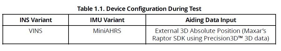
The following report shall analyze the aerial GNSS-denied navigation performance of the IL-VINS (Visual Inertial Navigation System) with Maxar’s Raptor vision-based positioning capability. Raptor determines absolute visual-based positioning from real-time imagery by referencing onboard, 3m accurate, satellite-based Precision3D three-dimensional maps. This study will exhibit the sensor fusion performance in GNSS-denied conditions of Inertial Labs’ INS with Maxar’s Raptor software development kit (SDK). Raptor can provide absolute 3D positioning aiding data estimates to the INS’s extended Kalman filter for seamlessly providing highly accurate PNT information to end-user applications. The following paper will depict results from two fixed-wing vehicle scenarios operating at low above ground level (AGL) with variation in day/night conditions while using a Cessna 172-S test aircraft. Table 1.1 below depicts the IMU and aiding data input sources used for the VINS platform during the tests.
Description of Aiding Data Input:
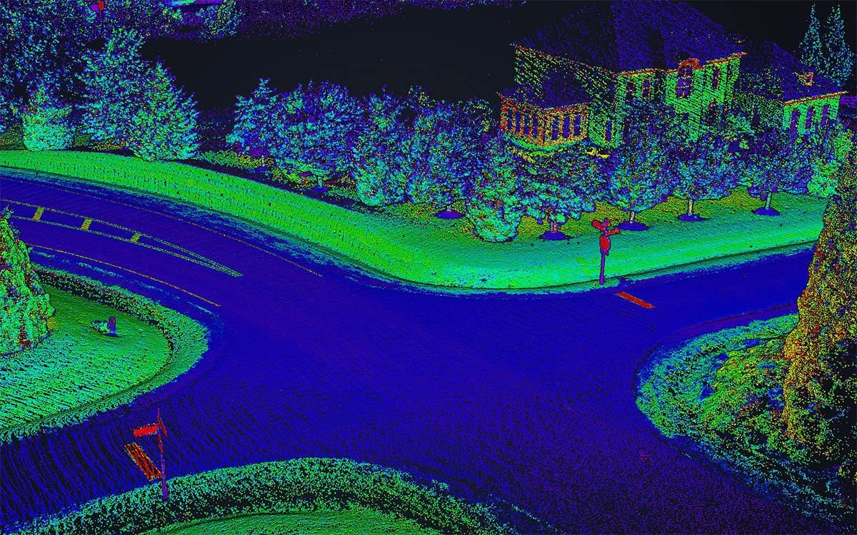
The VINS utilizes a robust 3D vision-based positioning algorithm (Maxar’s Raptor SDK) to estimate a vehicle’s absolute 3D position by applying Perspective and Point (PnP) principles to compare patterns captured from an onboard camera (day or IR camera) with satellite imagery-derived Maxar Precision3D maps. The position updates computed at a data rate of 1 Hz are supplied as an aiding data source to the INS sensor fusion algorithm for correcting the INS position and velocity within GNSS-denied environments.
Figure 1.1. Raptor provides 3D vision-based positioning to accurately estimate aerial platform 3D coordinates without GNSS information.
As shown in Figure 1.1 above, Raptor provides accurate aerial platform positions using 3D vision-based positioning techniques. Raptor uses breakthrough PnP algorithm improvements combined with high-quality, positionally accurate Precision3D textured mesh models of the Earth to provide low- and high-flying aerial platform accurate position estimates without using GNSS information. Raptor software runs on a single low-cost, commodity single board computer fed by existing and commodity fixed or gimballed visible or infrared video feeds. This software and data have been designed for commodity hardware, making them inherently modular and highly adaptable to various platforms using current and emergent commercially available components.
The following study will demonstrate the capability and accuracy of an Inertial Labs INS sensor fusion system, enhanced by 3D visual-based position estimation from Maxar’s Raptor SDK. It will evaluate the effectiveness of this system in GNSS-denied navigation across various platforms, including fixed-wing, multirotor, and VTOL, operating within day and night conditions at varying AGL altitudes due to variation in the terrain’s ground elevation.
2. Aerial Test Platform & Setup
A Cessna-172 Skyhawk aircraft was used as the primary aerial test vehicle for the flight test within this report. Attached are some figures that showcase how the GNSS antennas were mounted on the aircraft, Pitot-static tube mounting, and setup of the VINS.
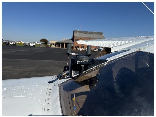
Figure 2.0. Mounting of Maxtena GNSS Antenna (M10HCT-A-TNC)
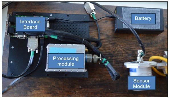
Figure 2.1. Interface Connection Diagram & Setup of VINS
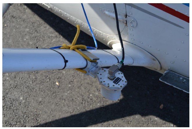
Figure 2.2. Mounting of the Sensor Module on the Wing Strut
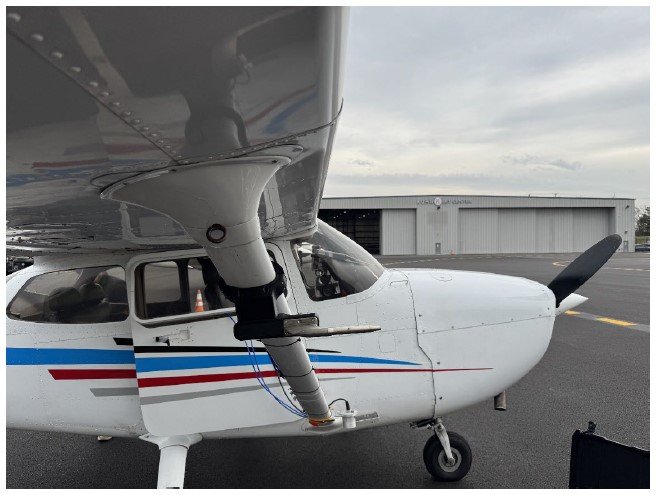
Figure 2.3. Mounting of the Pitot-Static Tube on the Wing Strut (Away from the Propeller Slip Stream)
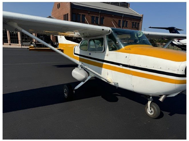
Figure 2.4. Cessna 172-S Test Aircraft
3. Comparative Performance Plots & Analysis of Flight 1 – Cessna 172-S Aircraft (Day Camera)
The section below shall provide performance plots on position error during the flight test duration, from the real-time results to a tightly coupled post-processed reference trajectory. The post-processed reference trajectory (ground truth) was generated using Inertial Explorer by tightly coupling raw GNSS observables, GNSS corrections using precise-point positioning, and raw IMU data collected from the reference INS systems.
Motion Path Trajectory:
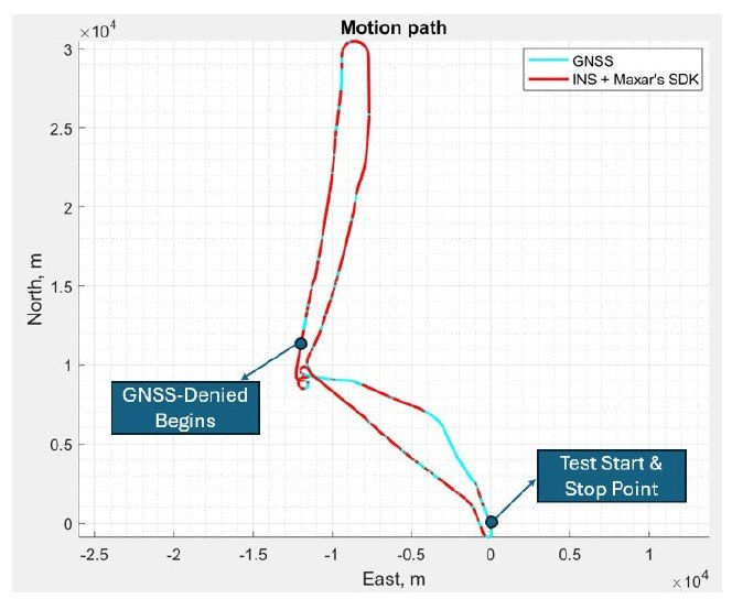
Figure 3.1. Motion Path Trajectories of GNSS (ground truth) and VINS
Figure 3.1 presents GNSS-denied begins after a figure-8 maneuver is conducted for magnetometer calibration (specifically for VINS) at the target cruise altitude (~3200ft above mean sea level). The “figure-8” maneuver consists of two 360-degree coordinated turns at a constant turn rate and roll angle in the clockwise and counterclockwise directions at a specific flight altitude. Once this maneuver is completed, the magnetometer’s field calibration parameters are estimated during operation and applied to the INS heading estimate when GNSS is disabled or lost.
INS Position Estimation Accuracy:
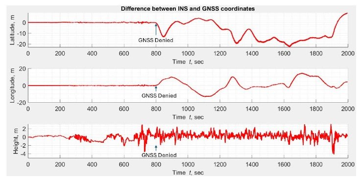
Figure 3.2. INS Position Error Estimation Throughout the Flight Duration
Figure 3.2 above showcases a bounded INS 3D position error of 20m during the entire flight duration. With Maxar’s Raptor software providing the INS with accurate, low-latency position estimation, the INS can maintain its drift and provide continuous positioning APNT output to a wide range of end-user platforms (i.e., flight control systems of fixed-wing and multirotor platforms). The altitude error of the flight doesn’t exceed 2m primarily due to two sources of altitude aiding: the computer vision-based position estimate and the internal barometer of the INS. Moreover, accurate position estimation allows the INS to yield precise velocity estimation throughout the flight, as exhibited in Figure 3.3 below.
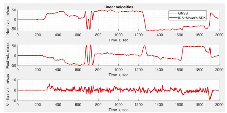
Figure 3.3. Comparison Between INS and GNSS Velocity Estimation Throughout the Flight Duration
Note: The INS estimated linear velocities are aligned with the GNSS estimated velocities. Figure 3.4 below presents the linear velocity estimation error plot to provide better observability of the velocity estimation performance during the flight.
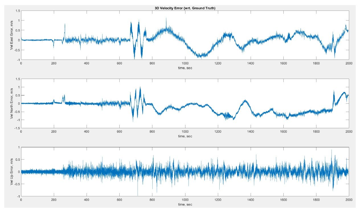
Figure 3.4. Velocity Estimation Error for Flight 1
4. Comparative Performance Plots & Analysis of Flight 2 – Cessna 172-S Aircraft (Boson-IR Camera – Night conditions)
Similar to flight test 1 procedures, the VINS with Maxar’s Raptor SDK was tested within night conditions with the FLIR Boson+ IR camera. The total distance travelled was approximately 58 km during this flight test. As presented in Figure 4.1 below, GNSS-denied begins after specific circular maneuvers were conducted for in-flight field magnetometer calibration (specifically for VINS) at the target cruise altitude (~3200ft above mean sea level).
Motion Path Trajectory:
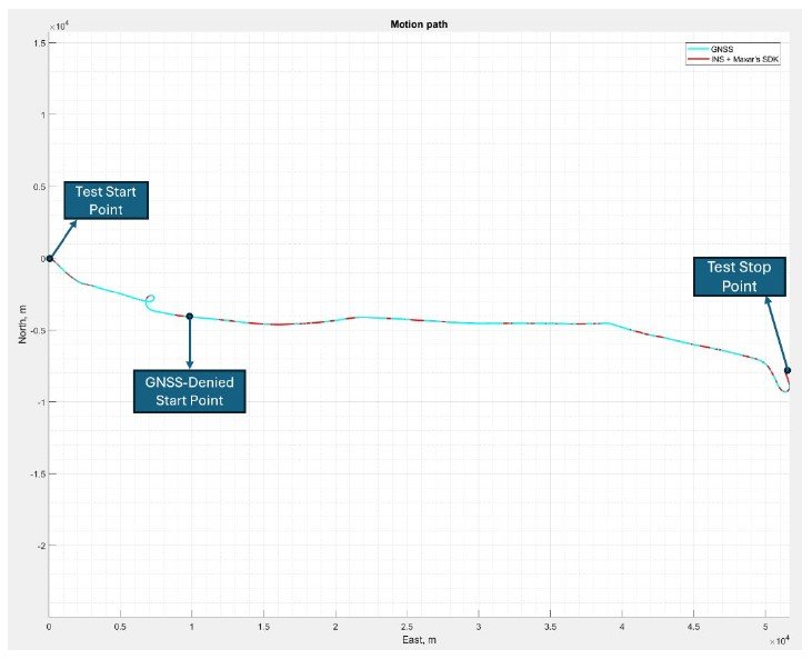
Figure 4.1. Motion Path Trajectories of GNSS (ground truth) and VINS for Flight 2.
INS Position Estimation Accuracy:
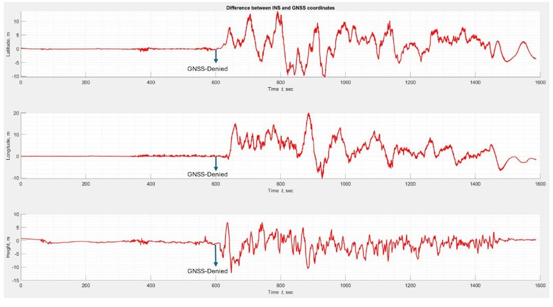
Figure 4.2. INS Position Error Estimation Throughout Flight 2’s Duration.
Figure 4.2 above showcases a bounded INS 3D position error of <15m RMS during flight duration. With Maxar’s Raptor software providing the INS with accurate, low-latency position estimation aiding data, the INS can maintain its drift and provide continuous positioning APNT output to a wide range of end-user platforms (i.e., flight control systems of fixed-wing and multirotor platforms) even during night-time conditions, with the VINS system being able to support separate Boson+ IR camera sensor module variants. Moreover, the altitude error of the flight doesn’t exceed 5m throughout the flight.
Figure 4.3 below showcases the INS’s velocity estimation derived from the absolute 3D position aiding supplied by Maxar’s Raptor SDK.
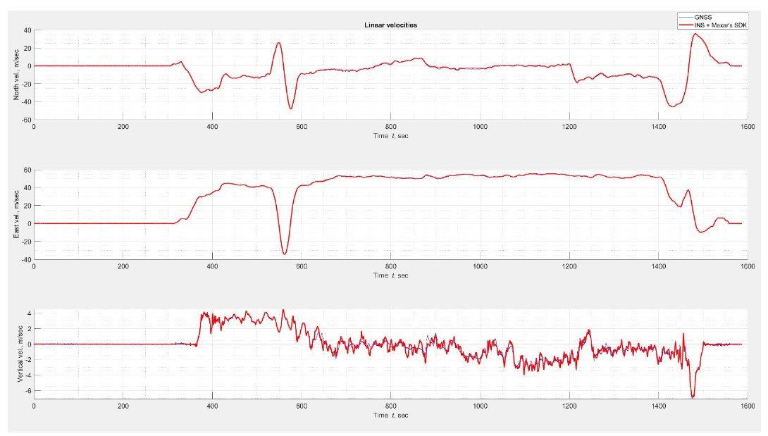
Figure 4.3. Comparison Between INS and GNSS Velocity Estimation Throughout Flight 2’s Duration
Note: The INS estimated linear velocities are aligned with the GNSS estimated velocities. Figure 4.4 below presents the linear velocity estimation error plot to provide better observability of the velocity estimation performance during the flight.
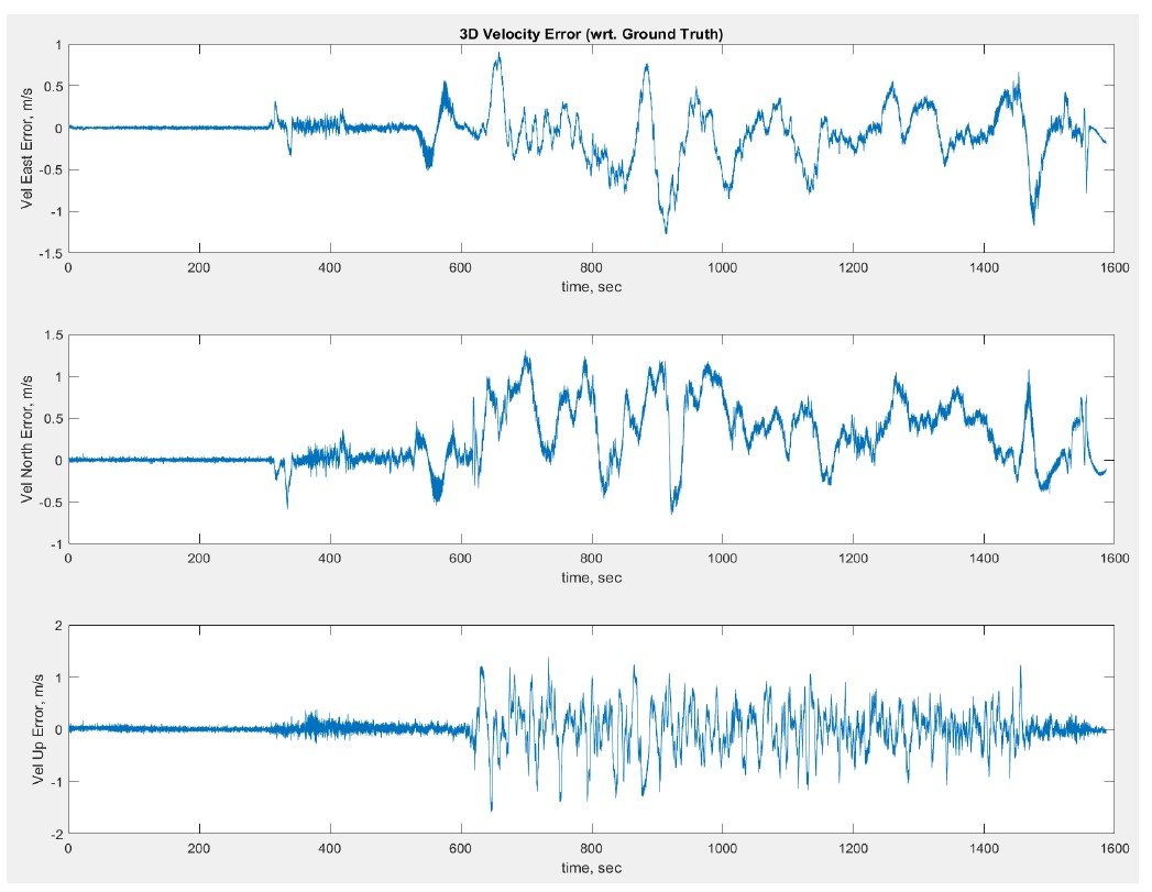
Figure 4.4. Velocity Estimation Error for Flight 2
Sample Captured Terrain Imagery Day (Left – Flight 1) VS Night (Right – Flight 2) Time Conditions:
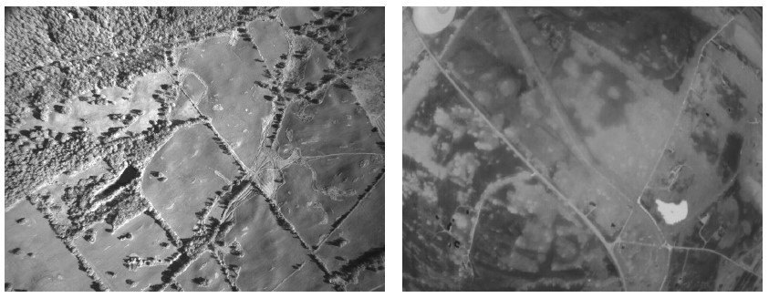
Figure 4.5. Comparison of Image Quality During Day Vs Night Sensor Module Variants of the VINS System.
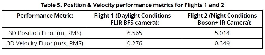
As observed from the results of the two flight tests depicted above, we can draw certain conclusions on the performance specifications of the integrated solution between Inertial Labs’ VINS and Maxar’s Raptor SDK:
This paper depicts how advanced, platform-agnostic sensor fusion algorithms can ensure continuous positional accuracy across various flight profiles and motion path trajectories within GNSS-denied and spoofed environments. The tightly coupled integration between the VINS and Maxar’s Raptor software is a significant path towards replacing traditional GNSS-aided PNT systems.