The rotation of our planet, which is seemingly imperceptible in everyday life, exerts a profound influence on many physical processes. One of the most significant and practical influences is its impact on inertial navigation systems (INS). These autonomous systems track the position and orientation of aircraft, ships, submarines, and even spacecraft. However, as research shows, even apparent stillness relative to the Earth’s surface does not mean the absence of motion in inertial space.
In this article, we will examine in detail how the Earth’s rotation manifests itself in the operation of INS, causing phenomena such as the Coriolis effect and the related Eötvös effect. We will explore the physical nature of these effects, their mathematical description, and how they affect the accuracy and reliability of inertial navigation. Understanding these subtle yet critical aspects is necessary for the development and operation of high-performance INS capable of providing precise navigation in a wide variety of conditions. Prepare to delve into the world of the rotating Earth and its unexpected influence on the technologies that define our movement.
Introduction
In the world of navigation and positioning technologies, inertial navigation systems hold a special place. Their autonomy and ability to provide data on position, velocity, and orientation without the need for external reference signals make them indispensable in a multitude of critical applications — from aviation and maritime fleets to space exploration and robotics. At the heart of INS operation are highly sensitive inertial measurement units (IMUs), equipped with accelerometers and gyroscopes that register linear accelerations and angular velocities [1].
However, despite all their technological sophistication, INS are susceptible to the influence of fundamental physical phenomena, one of which is the Earth’s rotation. The Earth, continuously rotating on its axis, creates inertial forces that can significantly affect the readings of IMU sensors. These effects, most clearly manifested as the Coriolis force and the related (to a lesser extent) Eötvös effect, can introduce errors into the calculations of position and orientation, especially during long-term autonomous navigation [2, 3].
Understanding precisely how the Earth’s rotation affects inertial sensors and how these effects manifest in the operation of inertial navigation systems (INS) is a key aspect for the developers of these systems. Ignoring or incorrectly compensating for these effects can lead to a significant accumulation of errors in determining the coordinates and orientation of objects. In this article, we will undertake a detailed investigation of the interaction between the Earth’s rotation and inertial navigation. We will reveal the physical nature of the Coriolis and Eötvös forces, analyze their mathematical descriptions, and consider the practical methods used in modern Inertial Navigation Systems (INS) to compensate for these effects and ensure reliable and accurate navigation in the conditions of a rotating Earth.
Section 1. Coordinate Systems
Correct accounting for the motion and orientation of objects in inertial navigation is impossible without a strict definition of coordinate systems. The following systems are typically used in navigation calculations:
- Earth-Centered Inertial (ECI) System. This is a coordinate system
 , relative to which the Earth’s rotation is not considered, as shown in Figure 1. The
  axis points to the vernal equinox. The
  axis coincides with the Earth’s axis of rotation. The
  axis completes the system to a right-handed Cartesian coordinate system. Motion in this system obeys the laws of Newtonian mechanics without the presence of any additional apparent forces.
 - Earth-Centered Earth-Fixed (ECEF) System. This system
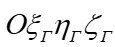 is rigidly fixed to the Earth. The center of the system coincides with the Earth’s center of mass. The X-axis passes through the intersection of the equator and the Greenwich meridian. The Z-axis coincides with the Earth’s axis of rotation. The Y-axis completes the right-handed coordinate system. This system takes into account the Earth’s rotation, and objects on its surface appear stationary relative to it [5].
 - Local Tangent Plane Frame (Navigation Frame). It has its origin at a point on the Earth’s surface whose position is given by latitude and longitude
 . The axes of the local tangent plane frame
  (or
(or  ) are oriented as follows: the
  axis is tangent to the parallel towards the East, the
  axis points North, and the
  axis points vertically upwards. Relative to this coordinate system, a free-azimuth coordinate system is rotated by an angle
  in the horizontal plane. A free-azimuth coordinate system is a local coordinate system that is not rigidly oriented concerning the geographical azimuth (direction to the north). Its orientation in the horizontal plane can change over time, usually following the orientation of the moving object (or in other words, it is a local navigation system) [5].
Figure 1. Coordinate Systems.
- Local Navigation System ENU (East-North-Up). This system is used on a moving object, such as an aircraft or a vessel (not shown in the figure). Sometimes the NED (North-East-Down) system is also used.
To determine the heading, roll, and pitch angles, equations such as Euler’s equations are used. These equations allow for the calculation of the object’s orientation based on the measured projections of the object’s absolute angular velocity and the computed projections of the navigation frame’s angular velocity. The geographical navigation frame ![]() is shown in Figure 2.
is shown in Figure 2.
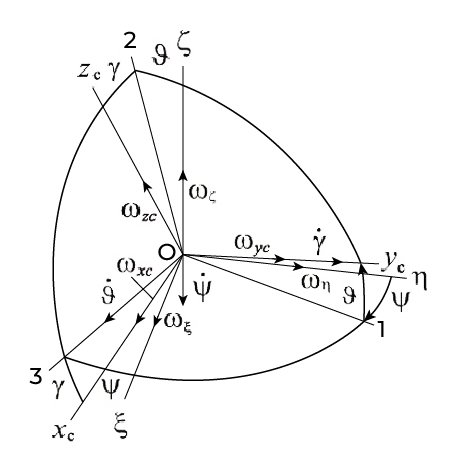
Figure 2. Geographical and Navigation Frames.
The ![]() axis points North;
axis points North; ![]() is the body frame; the angles
is the body frame; the angles ![]() are yaw (heading), pitch, and roll, respectively;
are yaw (heading), pitch, and roll, respectively; ![]() are the projections of the navigation frame’s angular velocity;
are the projections of the navigation frame’s angular velocity; ![]() are the projections of the absolute angular velocity measured by gyroscopes;
are the projections of the absolute angular velocity measured by gyroscopes; ![]() are the projections of the relative angular velocity.
are the projections of the relative angular velocity.
Because the absolute velocity is equal to the sum of the relative and transport velocities: 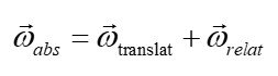
The sums of the projections onto the axes O1, O2 and O3 will be of the form (1):
 (1)
(1)
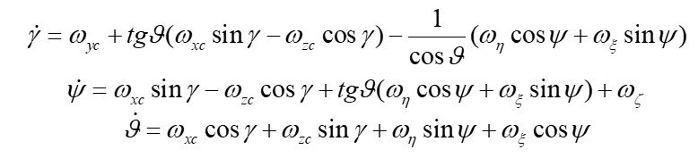
Equations (1) can be expressed in vector-matrix form as (2):
 (2)
(2)
The angular velocities ![]() are integrated, and based on the obtained yaw, pitch, and roll angles, the Direction Cosine Matrix (DCM) is calculated as (3):
are integrated, and based on the obtained yaw, pitch, and roll angles, the Direction Cosine Matrix (DCM) is calculated as (3):
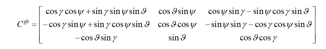 (3)
(3)
A drawback of the first two equations in (1) is their incorrectness when ![]() (This phenomenon is also known as “Gimbal Lock”).
(This phenomenon is also known as “Gimbal Lock”).
Quaternions (Rodrigues-Hamilton parameters), unlike Euler angles, are not subject to the Gimbal Lock problem, and therefore, the equations of motion written using quaternions do not degenerate at any orientation [5, 6]. Relations (4) are used for the transition from Euler angles to Rodrigues-Hamilton parameters:
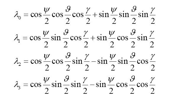 (4)
(4)
The DCM through the quaternion parameters can be represented in the following form (5):
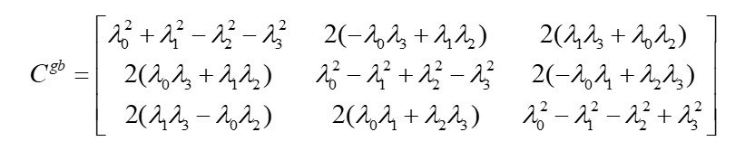 (5)
(5)
Correspondingly, using the components of matrix (5), the orientation angles can be obtained (6):
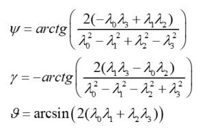 (6)
(6)
Section 2. The Coriolis Effect
The Coriolis force is a fictitious force that arises in a rotating frame of reference, such as the Earth’s frame of reference. It affects the motion of objects, deflecting their trajectory. In inertial navigation systems (INS), the Coriolis effect manifests as false accelerations and angular velocities caused by movement over the surface of the rotating Earth. If these false signals are not accounted for, the INS begins to misinterpret motion, especially at high speeds (for example, in aircraft, rockets, or UAVs) [2].
The angular velocity of the Earth’s rotation ![]() at latitude
at latitude ![]() is expressed as (7):
is expressed as (7):
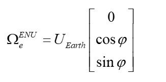 (7)
(7)
where ![]() .
.
The Coriolis acceleration in its general form is as follows (8):
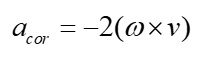 (8)
(8)
The projections of the Coriolis acceleration onto the axes of the geographical navigation frame by expanding the determinant (9):
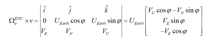 (9)
(9)
Substituting (9) into (8), we obtain (10): 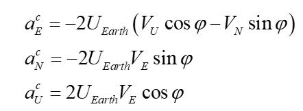 (10)
(10)
Assume that an object is moving with a velocity ![]() at a latitude
at a latitude ![]() . We take the other components to be zero. Then, the projections of the Coriolis acceleration will be equal to:
. We take the other components to be zero. Then, the projections of the Coriolis acceleration will be equal to:
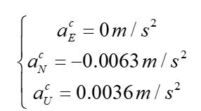
Without compensation for these components during the integration of accelerations, a growing error will occur in the determination of velocities and coordinates.
Considering that accelerometers measure apparent acceleration, we will sum the components of the gravity vector with the components of the Coriolis acceleration (10) and the relative acceleration (11), resulting in the projections of the apparent acceleration vector of the navigation frame’s origin onto its axes (12): 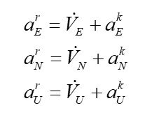 (11)
(11)
where ![]() are accelerations related to the curvature of the object’s movement along the spherical surface of the Earth.
are accelerations related to the curvature of the object’s movement along the spherical surface of the Earth.
 (12)
(12)
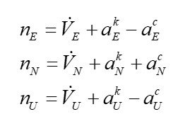
After solving the problem of projecting the apparent accelerations from the body frame to the geographical frame, expressions (12) are formed. This reprojection is carried out using the DCMs. However, when navigating along the Earth’s surface, it is necessary that only the accelerations of relative motion ![]() are fed to the inputs of the first integrators. Consequently, the Coriolis accelerations and the accelerations associated with the curvature of the object’s movement along the spherical surface of the Earth must be compensated for. Thus, the following quantities (13) must be assumed as the inputs of the first integrators (13):
are fed to the inputs of the first integrators. Consequently, the Coriolis accelerations and the accelerations associated with the curvature of the object’s movement along the spherical surface of the Earth must be compensated for. Thus, the following quantities (13) must be assumed as the inputs of the first integrators (13):
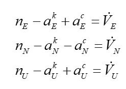 (13)
(13)
Below is a conditional block diagram of the INS implementation (Figure 3).
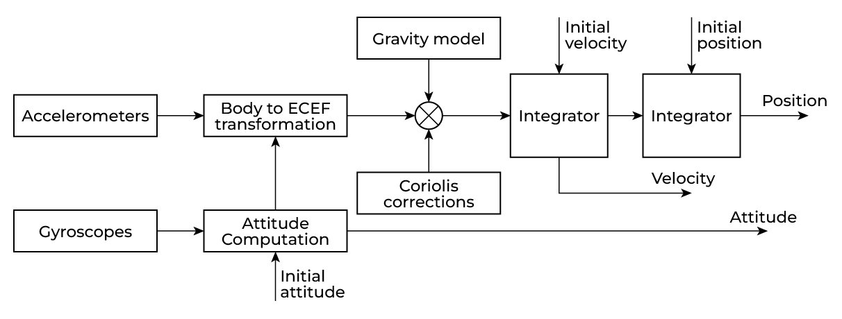
Figure 3. Block diagram describing the implementation of INS in a local horizontal coordinate system [7].
As can be seen, for correct operation, corrections are introduced for “harmful” accelerations to obtain only the accelerations of relative motion ![]() .
.
A few words should also be said about the gravitational model. The gravitational model is used to compensate for the gravitational influence on the accelerometer readings. For the INS to accurately determine the object’s motion (velocity, position, and orientation), it is necessary to isolate the actual kinematic acceleration from the accelerometer measurements. Only kinematic acceleration is caused by the object’s movement. It can also be used to estimate and compensate for the zero bias of the INS vertical channel accelerometer. The calculated value is subtracted from the measured acceleration readings.
There are various models, including simpler ones such as the WGS-84 ellipsoid gravity formula and more complex ones like EGM2008 [8].
Subsection. The Eötvös effect
The Eötvös effect refers to the change in apparent gravity that depends on the horizontal velocity of movement along lines of latitude, particularly when moving east or west, which is related to the Earth’s rotation [3]. Accelerometers register this change as a change in gravity and can introduce errors in the INS if not accounted for.
The Eötvös effect is expressed by the formula (14):
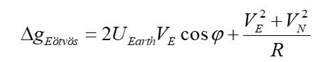 (14)
(14)
The first term in the formula corresponds to the Eötvös effect. The second term is a refinement that, under normal circumstances, is much smaller than the first.
As with the Coriolis effect, assume that an object is moving with a velocity ![]() at latitude
at latitude ![]() . We take the other components to be zero.
. We take the other components to be zero.
As a result, ![]() .
.
The Eötvös effect can be detected, but only with very sensitive accelerometers (the accelerometer must have a sensitivity of at least 10–50 μg), since it causes acceleration changes of only a fraction of a percent of g. However, even with good sensitivity, the Eötvös effect is primarily detected at high speeds, such as those of aircraft, satellites, and rockets. When walking, driving a car, or on a drifting ship, it is negligible.
Section 3. Earth’s Rotation and Angular Velocity (Or Why Only High-Precision FOG/MEMS Can Detect Earth’s Rotation)
On a base stationary relative to the Earth, the components of the angular velocity vector of the local-level (tangent plane) frame are given as follows (15):
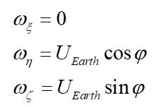 (15)
(15)
As is known, gyroscopes measure absolute angular velocities (16):
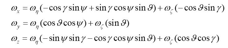 (16)
(16)
Determining the heading relative to the geographic North using a gyroscope is called gyrocompassing [9]. The direction to the North lies in the plane defined by the vertical, known from the position, and the direction of the Earth’s rotation vector ![]() . A gyroscope with a bias stability of less than 0.1°/h is capable of detecting
. A gyroscope with a bias stability of less than 0.1°/h is capable of detecting ![]() . However, to measure the orientation of the vector better than 0.5°, the measurement uncertainty must be better than 1% when measuring the magnitude of this vector (Figure 4). The Earth’s rotation rate, as mentioned earlier, is 7.29e-5 rad/s, or approximately 15°/h. Therefore, 1% of 15 °/h is 0.15°/h. Accordingly, with better gyroscopes, the accuracy of gyrocompassing is significantly improved.
. However, to measure the orientation of the vector better than 0.5°, the measurement uncertainty must be better than 1% when measuring the magnitude of this vector (Figure 4). The Earth’s rotation rate, as mentioned earlier, is 7.29e-5 rad/s, or approximately 15°/h. Therefore, 1% of 15 °/h is 0.15°/h. Accordingly, with better gyroscopes, the accuracy of gyrocompassing is significantly improved.
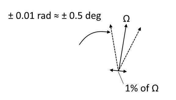
Figure 4. The relationship between the measurement uncertainty of the vector components of ![]() (±1% of its magnitude) and the uncertainty in calculating its direction.
(±1% of its magnitude) and the uncertainty in calculating its direction.
Attitude and Heading Reference Systems (AHRS) are used to determine orientation and heading. In a medium-accuracy AHRS, a magnetic compass is used to determine heading, but higher accuracy requires a gyrocompass.
Modern and inexpensive gyrocompasses are most often implemented using FOG (Fiber Optic Gyroscope), as it possesses the necessary bias stability and accuracy that surpasses that of MEMS gyroscopes. An example of such a solution is the INS-FI from Inertial Labs.
Section 4. The Inertial Labs GPS-Aided Inertial Navigation System INS-FI
The Inertial Labs GPS-Aided Inertial Navigation System, INS-FI, is the latest Inertial Navigation System (INS) developed by Inertial Labs, utilizing tactical-grade fiber optic gyroscope technology. The INS-FI is the result of over 25 years of experience in designing and supplying INS solutions for land, marine, and aerial platforms worldwide [10].
This system, the INS-FI, is an IP67-rated version of a new generation of super-ruggedized and EMC/EMI shielded INSs. The fully integrated INS-FI contains an Inertial Measurement Unit (IMU) that combines Fiber Optic Gyroscopes and MEMS Accelerometers, along with all constellations (GPS, GLONASS, GALILEO, QZSS, BEIDOU, and NAVIC), and a multiple-band GNSS receiver. It determines horizontal and vertical positions, velocity, and absolute orientation (Heading, Pitch, and Roll) for any device on which it is mounted. Horizontal and vertical Position, velocity, and orientation are determined with high accuracy for both motionless and dynamic applications (Figure 5).
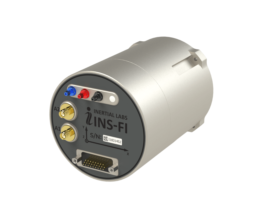
Figure 5. INS-FI.
Due to its high-performing FOG IMU, the INS-FI can measure GNSS-free Heading (True North) with less than 0.5° error, Horizontal & Vertical Positions with approximately 0.1% error of Distance Traveled for land applications, and five nautical miles per hour drift for aerospace (Unmanned Aerial Vehicles) applications without a GNSS signal.
INS-FI is fully compatible with the Inertial Labs developed VINS (Visual Inertial Navigation Systems) and SAMC (Stand-Alone Magnetic Compass).
The INS-FI contains Inertial Labs’ latest version of the onboard sensor fusion filter, state-of-the-art navigation and guidance algorithms, and calibration software.
Conclusion
Earth’s Rotation is a key factor influencing the operation of Inertial Navigation Systems (INS). Despite the apparent stillness of objects on the Earth’s surface, their motion in inertial space is subject to the planet’s rotation.
The Coriolis effect and the Eötvös effect are direct consequences of Earth’s rotation and can significantly affect the accuracy of INS. These phenomena must be taken into account during the development and operation of inertial navigation systems. Understanding the physical nature and mathematical description of these effects is critical for creating high-performance INS. Compensation for these effects (to a lesser extent for the Eötvös effect due to its smallness) is necessary to ensure reliable and accurate navigation under various operating conditions.
Being mounted on the rotating Earth, a gyroscope is subjected to the planet’s angular velocity of rotation. Fiber Optic Gyroscopes (FOGs) have several advantages that make them attractive for use in gyrocompasses. FOGs can provide high accuracy in angular velocity measurement with a low drift rate, which is critical for the precise determination of the direction to North. The absence of mechanical moving parts makes FOGs more reliable and resistant to vibrations and shocks. FOGs typically have smaller sizes and weights compared to traditional gyrocompasses.
Inertial Labs offers an excellent and inexpensive solution based on FOG – INS-FI. INS-FI can measure GNSS-free Heading (True North) with less than 0.5° error, Horizontal & Vertical Positions with approximately 0.1% error of Distance Traveled for land applications, and 5 nautical miles per hour drift for aerospace (Unmanned Aerial Vehicles) applications without a GNSS signal.
References
[1] IMU – Inertial Measurement Units.” Inertial Labs.
[2] “Coriolis Force.” Wikipedia, 4 Mar. 2020, en.wikipedia.org/wiki/Coriolis_force.
[3] Wikipedia Contributors. “Eotvos Effect.” Wikipedia, Wikimedia Foundation, 27 Oct. 2024.
[4] “Earth-Centered Inertial.” Wikipedia, 28 Aug. 2022, en.wikipedia.org/wiki/Earth-centered_inertial.
[5] BOSE, AMITAVA, et al. FUNDAMENTALS of NAVIGATION and INERTIAL SENSORS. PHI Learning Pvt. Ltd., 1 Jan. 2014.
[6] Wikipedia Contributors. “Quaternion.” Wikipedia, Wikimedia Foundation, 6 Dec. 2019, en.wikipedia.org/wiki/Quaternion.
[7] Aboelmagd Noureldin. Fundamentals of Inertial Navigation, Satellite-Based Positioning and Their Integration. Heidelberg, Springer, 2013.
[8] Wikipedia Contributors. “Theoretical Gravity.” Wikipedia, Wikimedia Foundation, 20 Sept. 2018, en.wikipedia.org/wiki/Theoretical_gravity.
[9] Lefevre, Herve C. The Fiber-Optic Gyroscope, Third Edition. Artech House, 31 Jan. 2022.
[10] “GPS-Aided INS-FI Datasheet Revision 1.9 FOG IMU-BASED GPS-AIDED INERTIAL NAVIGATION SYSTEM INS-FI.” https://inertiallabs.com/wp-content/uploads/2025/01/INS-FI_Datasheet_rev-1.9_Jan_2025.pdf