Scan patterns are a fascinating aspect of laser systems, including LiDAR, 3D scanners, and other spatial data acquisition technologies. A scan pattern defines the path along which a laser beam scans to collect data. Depending on the technology and task, the patterns can be linear, circular, spiral, zigzag, sectoral, or other shapes. In this article, we will examine the various types of scanning patterns and demonstrate how different patterns can be achieved with a single mechanical system.
Here are the sections that will be covered: Introduction to LiDAR, Differences between scanning patterns, and the Risley Prism Scanner.
Section 1. Introduction to LiDAR
Light Detection and Ranging (LiDAR) is a remote sensing technology that utilizes laser pulses to measure distances with remarkable accuracy. By emitting laser beams and analyzing their reflections from objects or surfaces, LiDAR systems create detailed three-dimensional maps of the environment. This technology has become a cornerstone in various industries, including geospatial mapping, autonomous vehicles, environmental monitoring, and construction.
LiDAR operates on the principle of time-of-flight (ToF), where the system calculates the distance to a target by measuring the time it takes for a laser pulse to travel to the object and back (Figure 1). This data is then processed to generate a point cloud—a collection of spatially referenced points that represent the scanned area or object in three dimensions.
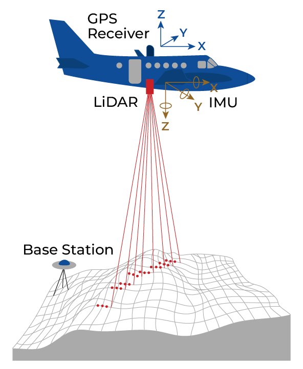
Figure 1. Conditional demonstration of LiDAR operation.
LiDAR is renowned for its high precision and ability to capture data in various environmental conditions. Some of its defining characteristics include:
- Accuracy: LiDAR can measure distances with centimeter-level precision.
- Versatility: It performs effectively in diverse settings, from dense forests to urban landscapes.
- High Resolution: The resulting datasets provide rich detail, allowing for intricate analysis.
- Speed: LiDAR systems can scan large areas, significantly reducing surveying time compared to traditional methods.
LiDAR’s versatility has led to its adoption across numerous fields:
- Geospatial Mapping: LiDAR is extensively used for creating high-resolution topographic and bathymetric maps.
- Autonomous Vehicles: Self-driving cars rely on LiDAR for obstacle detection, navigation, and spatial awareness.
- Environmental Monitoring: It helps in studying vegetation, monitoring coastal erosion, and tracking changes in ecosystems.
- Construction and Infrastructure: LiDAR aids in site analysis, construction planning, and structural monitoring.
- Archaeology: Researchers use LiDAR to uncover hidden structures and map historical sites.
Ongoing advancements in LiDAR technology aim to address these issues by developing more cost-effective, compact, and robust systems. LiDAR is a transformative technology that continues to redefine our ability to observe and interact with the world. As it evolves, its impact is expected to expand, unlocking new possibilities across a wide range of industries.
Section 2. Differences between scanning patterns
Various scanning patterns (or scan templates), such as circular, linear, and others, are used in LiDAR and other systems to obtain spatial data. The operation of the LiDAR deflection system determines a particular pattern. There are many options for deflection systems. Figure 2 illustrates a conventional LiDAR deflection system, comprising an emitter, a receiver, and a system of mirrors (or prisms) that deflect the beam [1].
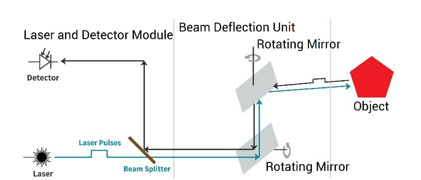
Figure 2. LiDAR Deflection System.
Mirrors or prisms can have different shapes and sizes. Depending on their geometry, the laser’s trace on the ground will differ. We will consider this in more detail below. Depending on the tasks, different mirrors or prisms are selected, for example, as shown in Figure 3 [2]. This is due to the requirement to scan only certain areas or within a specific angle.
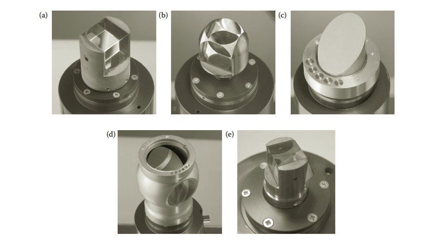
Figure 3. (a) Cube prism; (b) ball prism; (c) open face mirror; (d) spherical housing containing 45° mirror, and (e) pentaprism.
In addition to mechanical systems, there are microelectromechanical ones. Recently, they have been rapidly developing due to the growing demand for miniature lidars. In such devices, the deflection system consists of a miniature mirror suspended on a platform. The deflection is done by actuators, as shown in Figure 4 (a). In reality, such mirrors have the form shown in Figure 4 (b).
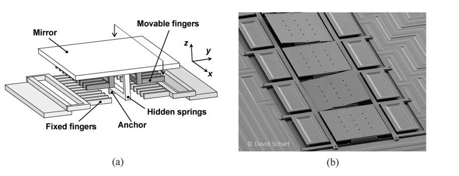
Figure 4. Structure of MEMS Deflection System.
Now, let’s consider how the shape and orientation of the mirrors (or prisms) affect the trace left by the beam, as shown in Figure 5 [3].
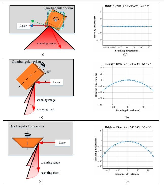
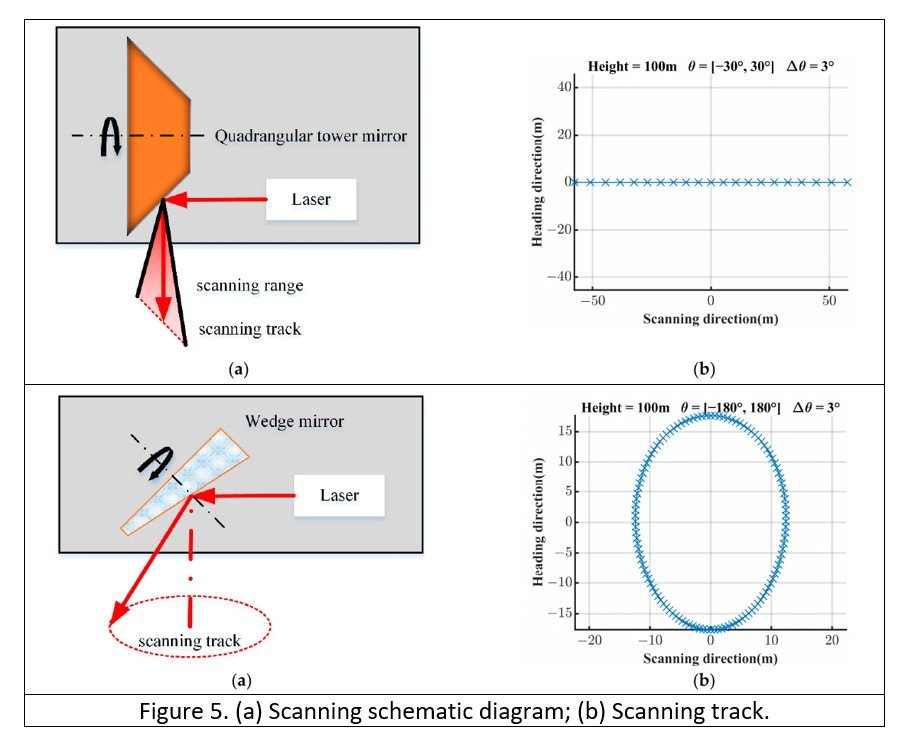
As we can see, different mirrors and prisms can form similar patterns, and at the same time, the same mirrors can create various patterns, depending on their geometric position.
Let’s take a look at Figure 6. The first pattern (on the left) is a zigzag (there is also a sine wave variant). Raster or Zigzag Scanning is used in ground systems and mobile platforms.
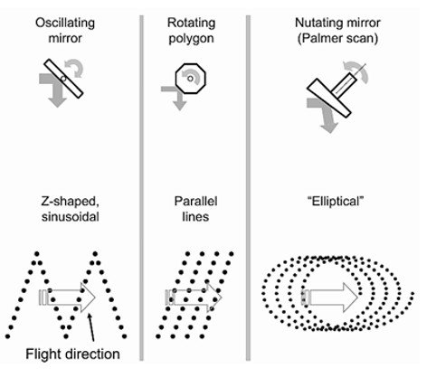
Figure 6.
The second option is a linear pattern (in the middle). Often used in airborne LiDAR systems and ground-based scanners.
The last pattern (on the right) is Rotary or Circular Scanning. It is used in scanners equipped with a rotating mirror or a rotating device.
Some LiDARs have a more complex pattern, which resembles a spirograph pattern, for example, as shown in Figure 7 [4].
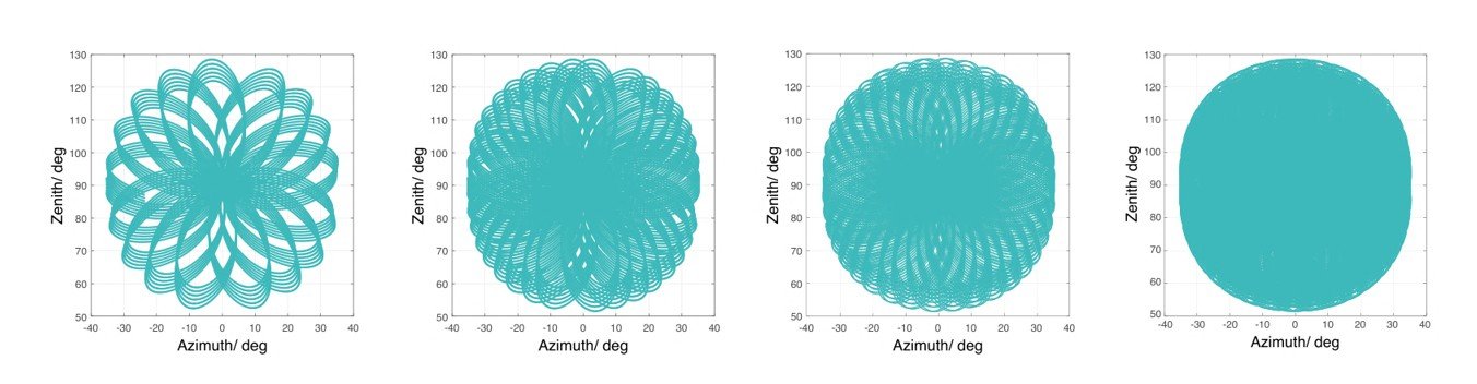
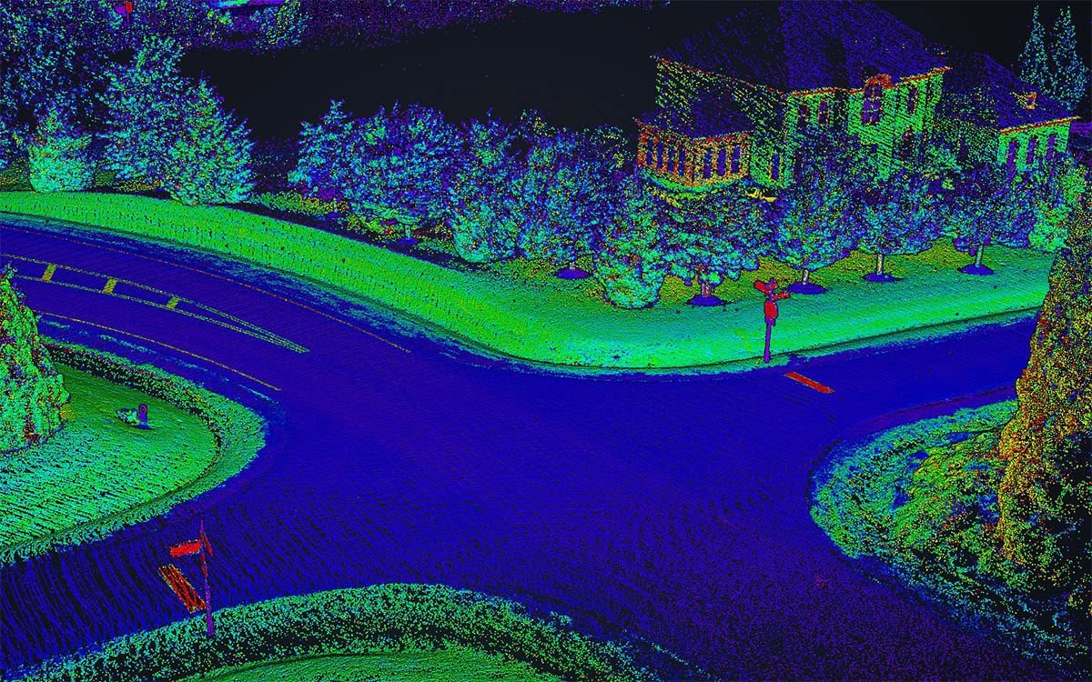
Figure 7. The typical point cloud patterns of the Livox Avia over an extended period.
Such a pattern allows you to achieve a very high density of a point cloud without movement, i.e., in a static setting. Such a pattern is obtained by using the Risley Prism Scanner.
Section 3. The Risley Prism Scanner
The Risley Prism is an optical device used to control the direction of a laser beam or other optical beam by independently rotating two prisms relative to each other [5]. The prisms are typically wedge-shaped and oriented in a manner that allows them to be rotated around their optical axes (Figure 8).
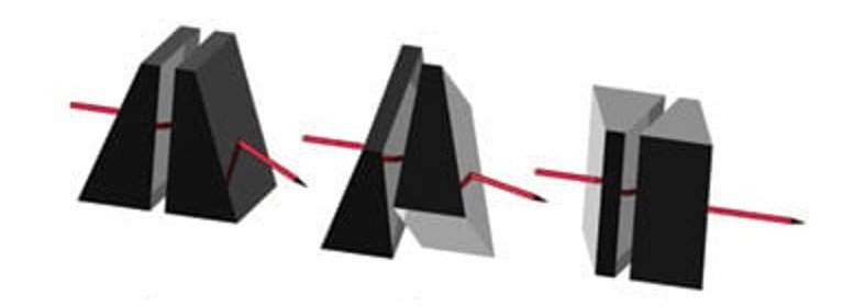
Figure 8. The Risley Prizm.
Parametric equations of point coordinates on a plane can be expressed as follows:
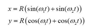
Where R is the beam displacement relative to the starting point, ω1 and ω2 are the rotation speeds of the first and second prisms, respectively.
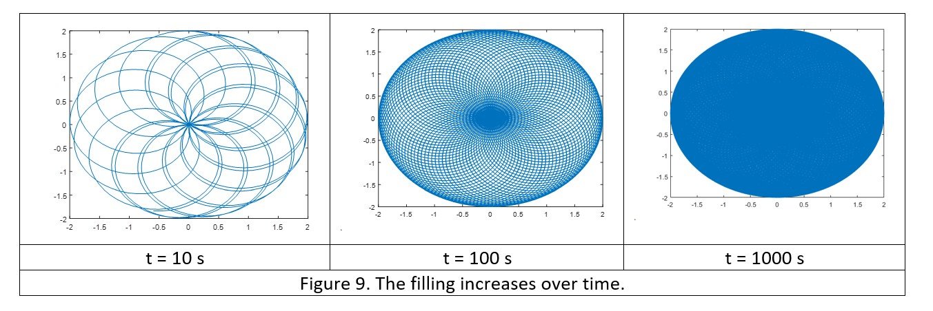
For clarity, we will model these equations and examine the results. Let R = 1, ω1 = 10√2, ω2 = 1. Time t 10, 100, 1000 seconds. The results are shown in Figure 9. As you can see, the longer the prisms rotate, the more the circle is filled.
Now, we change the rotation speeds: ω1 = 1 and ω2 = -1. That is, the prisms rotate at the same speed, but in different directions. As a result, we get a straight line, as shown in Figure 10. Unlike the previous case, this pattern remains constant over time.
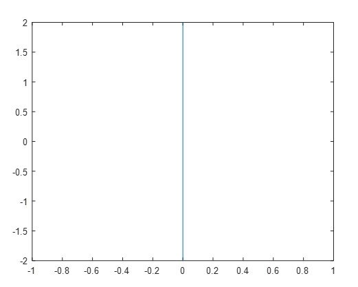
Figure 10. The rotation speed of the prisms is the same, but the direction of rotation is different.
With the same rotation speeds in one direction, we get a circle, as shown in Figure 11.
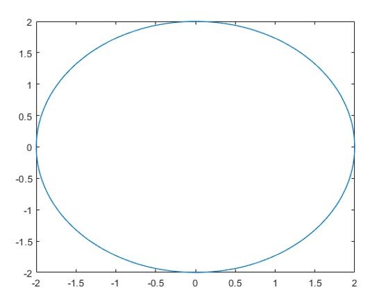
Figure 11. The rotation speeds are the same, and the directions are the same.
For the next experiment, we will maintain the same rotation direction but increase the speed of one of the prisms, ω1 > ω2. The result is shown in Figure 12.
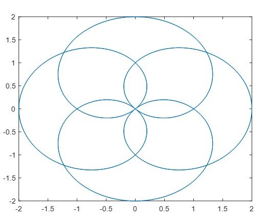
Figure 12. The speed of one of the prisms is higher, and the direction of rotation is the same.
Thus, by varying the speed and direction of rotation of the prisms, it is possible to achieve completely different patterns without changing the mechanical system. All these subtleties fall on the shoulders of optical system developers, but now you know how it works.
References
[1] lidar. “Velocity Determination from Lidar Point Cloud | in the Scan.” In the Scan, 27 Nov. 2023, blog.lidarnews.com/velocity-determination-from-lidar-point-cloud/. Accessed 13 Jan. 2025.
[2] Marshall, Gerald F, and Glenn E Stutz. Handbook of Optical and Laser Scanning. CRC Press EBooks, Informa, 23 July 2004. Accessed 3 May 2023.
[3] Zhou, Hao, et al. “Analysis of Internal Angle Error of UAV LiDAR Based on Rotating Mirror Scanning.” Remote Sensing, vol. 14, no. 20, 20 Oct. 2022, pp. 5260–5260, https://doi.org/10.3390/rs14205260. Accessed 15 Aug. 2024.
[4] “RESEPI Livox AVIA.” RESEPI, lidarpayload.com/home/resepi-livox-avia/.
[5] Application Note Risley Prism Scanner. https://www.thorlabs.com/images/tabimages/Risley_Prism_Scanner_App_Note.pdf
Foundation, 20 Sept. 2018, en.wikipedia.org/wiki/Theoretical_gravity.
[9] Lefevre, Herve C. The Fiber-Optic Gyroscope, Third Edition. Artech House, 31 Jan. 2022.
[10] “GPS-Aided INS-FI Datasheet Revision 1.9 FOG IMU-BASED GPS-AIDED INERTIAL NAVIGATION SYSTEM INS-FI.”