As autonomous systems are increasingly deployed in contested and GNSS-denied environments, navigation resilience has become a defining requirement for many armed forces. Inertial Navigation Systems (INS) are critical in this environment, and now Inertial Labs is developing the next evolution of INS with an additional layer of environmental awareness, vision.
Inertial Labs’ has pioneered the development of Visual Inertial Navigation Systems – known as VINS – which is being operationally deployed as the next evolution of INS. By combining traditional inertial navigation with advanced visual odometry, VINS enhances positional accuracy and autonomy in challenging operational conditions including GNSS jamming and spoofing scenarios.
From INS to VINS: What has changed?
A traditional INS relies on an Inertial Measurement Unit (IMU), comprising gyroscopes, accelerometers, magnetometers, fused with GNSS inputs and filtering algorithms to calculate position, velocity, and attitude. In GNSS-available environments, this architecture performs exceptionally well. However, in GNSS-denied conditions, even high-grade inertial systems will gradually accumulate positional drift over time.
VINS addresses this limitation by introducing visual odometry as an additional aiding source. Rather than relying solely on satellite signals or inertial estimation, VINS uses a ground-facing camera to measure motion relative to the surface below.
But what exactly is visual odometry? It is not image stabilisation or optical horizon sensing. Instead, it is a dedicated velocity measurement mechanism that tracks identifiable reference points on the ground as the UAV travels over the earth. By calculating how these reference points shift between frames, the system determines ground velocity with high precision.
This velocity data is then fed into the INS algorithms as a correction source, reducing drift, and improving overall positional accuracy.
How VINS works: system architecture
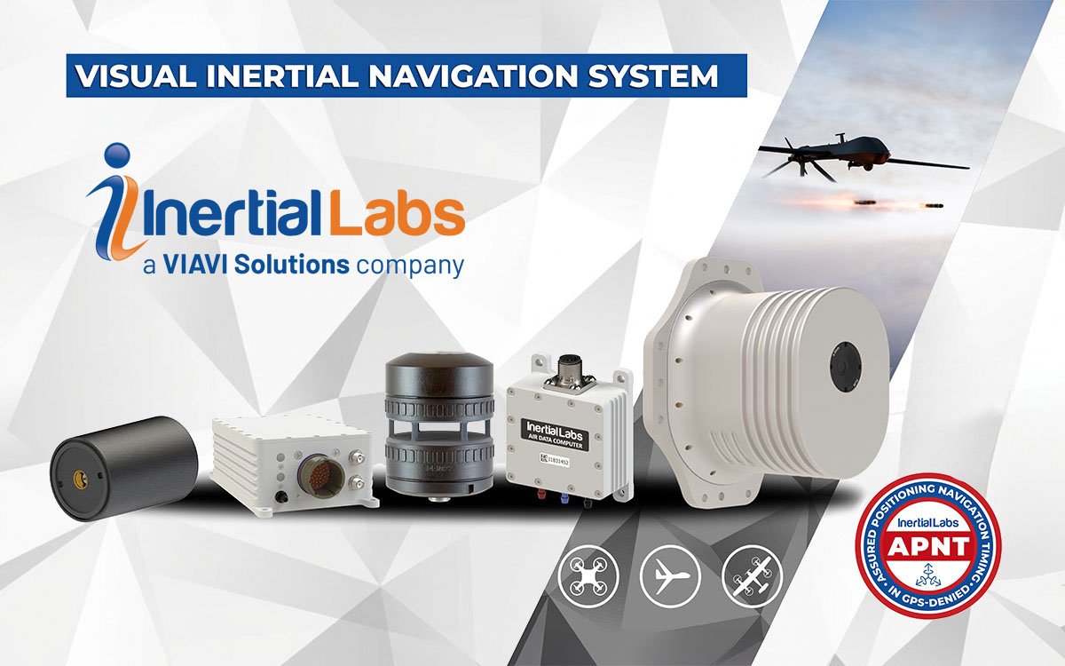
Unlike a single-box INS, VINS is a modular system consisting of three primary elements:
1. Processing module
This unit gathers all incoming data and performs the sensor fusion and navigation calculations.
2. Sensor module
This includes:
- A specialised camera designed for ground observation
- Inertial sensors (accelerometers, gyroscopes, magnetometers)
The camera will then continuously observe the terrain below the UAV. Proprietary algorithms identify and track distinct ground features to calculate velocity through visual odometry.
3. Optional air data source
Depending on the platform, this may include:
- Air Data Computer (ADC) for fixed-wing UAVs
- Digital wind speed sensor for multirotor platforms
This modular approach allows flexibility in installation and integration, particularly across different UAV configurations.
Why visual odometry matters
The key differentiator of VINS lies in how it measures velocity.
In GNSS-denied environments, traditional INS systems rely solely on inertial integration to estimate position. Over time, small sensor biases accumulate and lead to drift. By introducing an independent velocity measurement source, derived from ground observation, VINS adds a secondary correction mechanism.
When GNSS is available, the system can tune and calibrate internal offsets between GNSS, inertial and visual inputs. When GNSS is lost or degraded, previously calibrated relationships are used to maintain higher navigation accuracy than inertial-only solutions.
This makes VINS particularly relevant for:
- UAV operations in jamming or spoofing environments
- Low-altitude missions over structured terrain
- Tactical platforms operating without reliable satellite coverage
- Autonomous flight profiles requiring enhanced drift control
Importantly, this is not a vision-based mapping or terrain-matching system. VINS does not compare images to stored maps for geolocation. Instead, it uses camera-derived motion to improve inertial accuracy – a more streamlined and integration-friendly approach.
A fully integrated solution
Current camera-based velocity sensors are typically standalone devices that require integration with third-party INS systems. This dependency introduces engineering complexity, calibration challenges, and additional validation requirements.
VINS provides a fully integrated solution, eliminating the need for customers to source, synchronise, and validate disparate subsystems.This integration delivers several advantages:
- Unified filtering and sensor fusion architecture
- Reduced integration burden
- Simplified calibration and offset management
- Faster deployment into operational platforms
The result is a system that can be adopted without significant redesign of existing navigation stacks.
Platform flexibility
VINS has already been deployed on small aircraft and VTOL platforms.The system is adaptable across various UAV types, provided the platform can support the required payload weight and ground-facing optical field of view.
VINS is optimised for aerial applications since the camera must observe the ground surface. It is not intended for marine or subsurface use and differs from optical Attitude and Heading Reference System (AHRS) systems that use cameras for orientation tracking.
For multirotor UAVs, digital wind speed sensing replaces traditional pitot-based airspeed measurement, avoiding airflow disturbances caused by rotor wash. For fixed-wing aircraft, standard air data computers can be used.
Enhancing resilience with optional capabilities
VINS also supports optional integration with additional resilience technologies, including:
- Controlled Reception Pattern Antennas (CRPA) for anti-jamming protection
- Software Defined Radio (SDR) solutions for alternative positioning methods
- M-code or advanced GNSS receiver options
These features allow VINS to be incorporated into broader navigation resilience architectures without requiring structural redesign.
Looking ahead: visual navigation and AI
We’re pleased that customer feedback so far has been positive, particularly in applications where navigation continuity under degraded GNSS conditions is critical. The integrated nature of the solution and measurable improvements in accuracy compared to inertial-only systems have interested UAV developers seeking enhanced autonomy.
Specific performance figures are platform-dependent; however, the addition of visual velocity correction demonstrably improves drift control and positional stability during GNSS outages.
The current generation of VINS focuses primarily on visual odometry for velocity correction. However, development plans extend toward broader visual navigation capabilities.
Future iterations may incorporate:
- Expanded use of visual data beyond velocity estimation
- Advanced algorithmic refinement
- AI-assisted processing to improve robustness under varying weather, terrain, and lighting conditions
As autonomy demands increase, navigation systems will need to operate with greater independence from external infrastructure. VINS represents a foundational step toward that objective.
Conclusion
VINS is not simply an INS with a camera attached. It is an integrated visual-inertial navigation architecture solution designed to improve accuracy, resilience, and autonomy in challenging environments.
By combining proven inertial navigation with dedicated visual odometry and flexible modular integration, Inertial Labs delivers a solution that bridges the gap between traditional INS and next-generation autonomous navigation systems.
For UAV developers and users operating in GNSS-contested environments, VINS offers a practical and scalable path to improved performance without excessive integration burden.


